
A burnt or defective cylinder head gasket is determined by the following signs:
- Reduced engine power.
- Coolant level drops, with white steam coming out of the exhaust pipe.
- Decreasing engine oil level.
- The presence of coolant in the engine oil. In this case, the oil level increases. If there is coolant in the engine oil, the engine oil becomes gray and has foam bubbles.
- Presence of motor oil in the coolant.
- Intensive bubbling of coolant.
- Decreased compression in two adjacent engine cylinders.
Removal
Turn off the ignition and remove the ground wire from the battery.
Attention
- When disconnecting the wires from the battery terminals, the memory units of the control units erase the data on the recorded faults, so before disconnecting the wires, you must contact a workshop to recall the faults recorded in the memory. After connecting the wires to the battery terminals, it is necessary to activate and reprogram the electric windows, as well as the position of the rear-view mirrors and seats.
- If the car has a radio receiver with a code, then before disconnecting the wires from the terminals from the battery, check that there is a code to reactivate the receiver. Otherwise, the radio receiver can only be put into operation at a specialized station.
Remove the air filter cover. Loosen the clamp and disconnect the air pipe.
Unscrew the screws and remove the engine cover.
Disconnect the crankcase ventilation hose 2 from the cylinder head cover (Fig. 2.15) and turn it to the side.
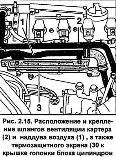
Supercharged engine. Disconnect the boost pipe 1 (Fig. 2.15) from the combination valve in the cylinder head cover. Unscrew and remove the heat shield 3.
Drain the coolant from the engine cooling system.
Unscrew the expansion tank from the bracket and move it to the side along with the hoses connected to it.
Set the front body panel to the service position.
Clean the spark plugs using a brush, vacuum cleaner or compressed air to prevent dirt from getting into the engine cylinders after the spark plugs are removed. Remove the spark plugs.
Remove the fuel line mounting bolts and remove the low pressure hose from the pressure regulator (see fig. 2.16). Do not open the fuel system.
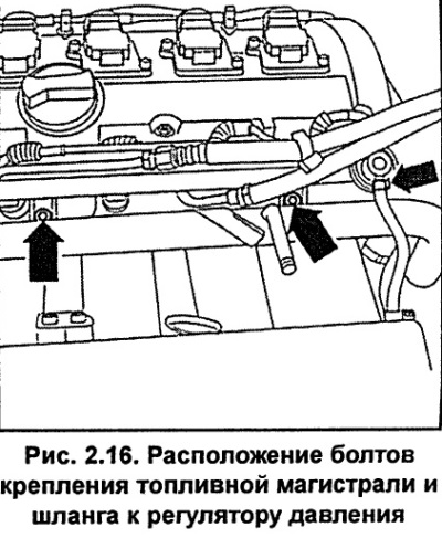
Safety note: The fuel system is under pressure. Before disconnecting the fuel lines, relieve the pressure in the fuel system. To do this, cover the connection with a rag and, being careful, disconnect. When disconnecting the system components, fuel may splash, so use glasses to protect your eyes from fuel getting into them.
Remove the fuel line with injectors from the intake manifold and place it on a clean rag in the rear of the engine compartment.
Disconnect low pressure hose 1 (Fig. 2.17) from the fuel vapor recovery valve (containers with activated carbon).
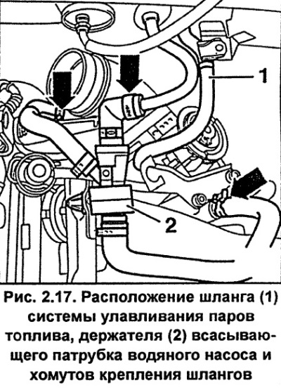
Loosen the clamps and remove the cooling system hoses (see fig. 2.17).
Release the holder 2 (Fig. 2.17) of the water pump suction pipe from the retainer and remove it together with the hoses.
Remove the upper coolant pipe from the rear of the cylinder head.
Loosen the clamp and disconnect the air pipe from the throttle body.
Disconnect the accelerator cable from the throttle body.
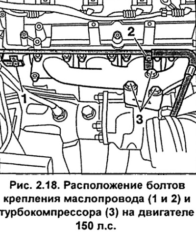
Engine 150 hp. Unscrew bolts 1 and 2 (Fig. 2.18) securing the oil line and bolts 3 securing the turbocharger.
Engine 150 hp. Unscrew the support stand located between the cylinder head and the intake pipe near the generator.
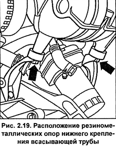
Engine 125 hp. Unscrew the lower suction pipe mount from the rubber-metal supports (see fig. 2.19). Also, disconnect the electrical connectors and low pressure hose from the intake manifold length switching valve.
Remove the oil dipstick.
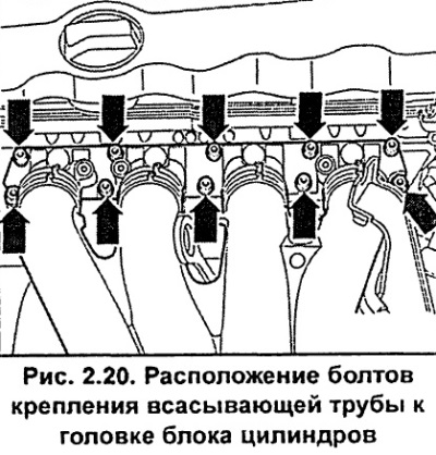
Unscrew the bolts and remove the intake pipe from the cylinder head (see fig. 2.20).
Label the electrical connectors and disconnect them from the cylinder head.
Disconnect the upper and lower hoses from the radiator. To do this, remove the retaining clips on the side of the coupling, then disconnect the hoses.
Release the spring clip and remove the lambda sensor electrical connector from the holder and disconnect it.
Unscrew the exhaust pipe with the catalytic converter from the exhaust manifold.
Remove the upper timing belt cover and set the piston of the first cylinder to TDC.
Loosen the timing belt tension and remove it from the camshaft pulley.
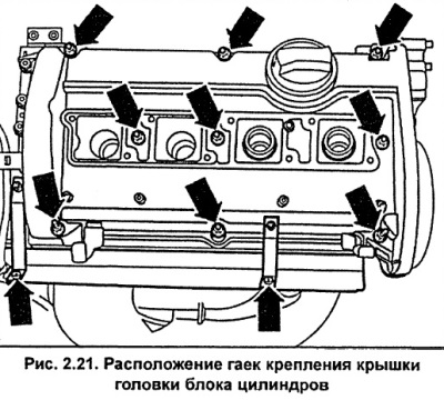
Unscrew the cylinder head cover mounting nuts and remove it together with the seal (see fig. 2.21).
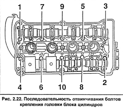
In the sequence from 1 to 10 shown in Figure 2.22, unscrew the cylinder head mounting bolts. To unscrew the bolts, you must use an 8 mm Allen key.
Check that all lines, hoses and electrical connectors are disconnected from the cylinder head.
Remove the cylinder head from the engine and place it on two wooden blocks.
Remove the cylinder head gasket.
Installation
Before installing a new cylinder head, remove the plastic plugs designed to protect the exposed valves of the cylinder head.
The mating surfaces of the cylinder head and block must be clean. Use a hard plastic or wooden scraper to clean them. Be careful when cleaning, as the aluminum alloy is very easy to damage.
Check that carbon deposits have not entered the oil and water passages. This is especially important for the lubrication system, as carbon deposits can block the flow of oil to engine components. Clean the passages if necessary.
Clean the bolt holes in the cylinder block. Driving a bolt into an oil-filled hole can cause the block to burst due to hydraulic pressure.
Using a metal ruler and feeler gauge, check the flatness of the mating surfaces (see fig. 2.23). Deviation from flatness should be no more than 0.1 mm.
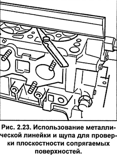
If there are small defects on the mating surface of the cylinder head, they can be removed by mechanical processing.
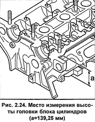
The height of the cylinder head after machining should be 139.25 mm (see fig. 2.24).
A cylinder head with cracks between the valve seats or the valve seat ring and the first thread of the spark plug can be installed, and their service life is not reduced. The head must be repaired if the crack width exceeds 0.5 mm.
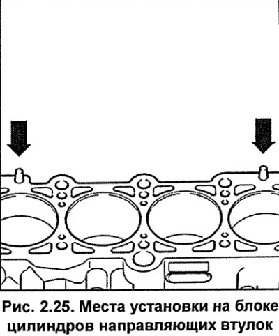
Check that the cylinder block has guide bushings installed to center the gasket and cylinder head (see fig. 2.25). If there are no bushings, install them.
When installing the cylinder head, it is necessary to use a new cylinder head gasket.
Remove the cylinder head gasket from its sealed packaging immediately before installing it on the cylinder block.
Check that the new cylinder head gasket is the same type as the original and that the TOP or OBEN marking is facing upwards. Position the new cylinder head gasket on the cylinder block surface on the guide pins. Check that the holes are correctly aligned with the cooling and lubrication system passages.
The engine has 125 hp.Before installing the cylinder head, return the timing belt tensioner lever to its original position.
Check that the crankshaft and camshaft are set to the position where the piston of the first cylinder is at TDC. If necessary, set them to this position.
Carefully install the head onto the cylinder block with the help of an assistant.
When installing, it is necessary to use new cylinder head mounting bolts.
Insert and hand tighten the cylinder head bolts.
Engine 150 hp Loosen bolts 1 and 2 (Fig. 2.26) securing the turbocharger support by two turns to eliminate possible distortions when installing the cylinder head.
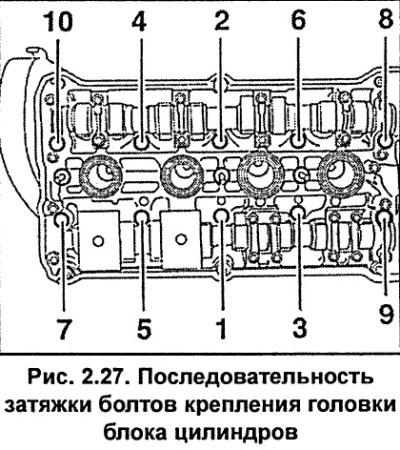
Gradually tighten the cylinder head mounting bolts in several stages in the sequence shown in Fig. 2.27.
Tightening torques for cylinder head bolts.
AJP/AWT Engine:
Step 1 - Tighten to 40 Nm;
Step 2 - Turn to 90°;
Step 3 - Turn to 90°
Engine AEB/ANB/APU/ADR:
Step 1 - Tighten to 60 Nm;
Step 2 - Turn to 90°;
Step 3 - Turn to 90°
Caution: Do not tighten the cylinder head mounting bolts on a warm engine. When installing a new cylinder head with a camshaft, after installing the cylinder head, lubricate the mating surfaces of the hydraulic tappets and camshaft cams with a thin layer of grease.
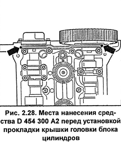
Before installing the inner cylinder head cover gasket, lubricate the transitions (including on the opposite side) from bearing caps to cylinder head with Loctite Ultra Black or AUDI D 454 300 A2 (see fig. 2.28). Install the cylinder head cover gasket.
Install the cylinder head cover and gradually tighten the cover mounting nuts in a crisscross pattern to a torque of 10 N·m.
Engine 150 hp. Bolt the turbocharger support to the cylinder block and turbocharger. The tightening torque of the bolts on the AWT engine is 25 Nm, and on the AEB/ANB/APU engine - 40 Nm.
Install the timing belt on the camshaft pulley and adjust its tension.
Install the V-belts and poly V-belts and adjust their tension.
Screw the exhaust pipe with the catalytic converter to the exhaust manifold.
Connect the electrical connector of the lambda sensor, install it into the holder and secure it with the spring clip.
Screw the suction pipe with new gaskets to the head and secure it with bolts, tightening them gradually crosswise to a torque of 10 Nm.
Engine 125 hp. Secure the lower part of the suction pipe to the rubber-metal supports.
Engine 150 hp. Screw the support stand between the cylinder head and the intake pipe and tighten the mounting bolts to a torque of 20 Nm.
Install the fuel line with injectors onto the intake pipe and secure with bolts, tightening them to a torque of 10 Nm.
Install and secure the holder 2 (Fig. 2.17) of the water pump suction pipe with a clamp.
Install spark plugs and ignition coils.
Install and secure the wires from the intake pipe and Hall sensor.
Bolt the upper coolant pipe to the rear of the cylinder head and the intake pipe and tighten the bolts to 10 Nm.
Install the expansion tank into the holder.
Engine 150 hp. Install the oil pipe and secure it with bolts to the cylinder head, tightening them to 20 Nm. Secure the turbocharger with a new gasket to the exhaust manifold and secure it with bolts, tightening them to 35 Nm.
Install the accelerator cable.
Connect the upper and lower hoses to the radiator.
Check that all hoses, lines and electrical connectors are connected as previously marked.
Replace the oil dipstick.
Check the engine oil level and top it up if necessary. If a new cylinder head is installed, the engine oil and oil filter must be replaced.
Fill the cooling system with fresh coolant.
Supercharged engine. Connect the boost pipe 1 (Fig. 2.15) to the combination valve and secure it with bolts to the cylinder head cover, tightening the bolts to a torque of 10 Nm. Install and screw on the heat shield, tightening the mounting bolts to a torque of 5 Nm.
Screw the crankcase ventilation pipe to the cylinder head cover, tightening the mounting bolts to a torque of 10 Nm.
Replace the air duct and air filter cover.
Connect the ground wire to the battery. Repeat the steps to memorize the position of the seats, mirrors, etc., and also set the time on the clock and enter the code into the radio.
Start the engine and warm it up to operating temperature. Turn off the engine and check the engine oil and coolant levels, as well as the tightness of all connections.
Caution: When disconnecting various electrical connectors, errors are stored in the memory that must be cleared after installation.
[The original source of the article can be found on the website AudiManual]