
Table of contents: Left cylinder head ↓ Right cylinder head ↓
Remove the cylinder head on a cold engine.
A burnt or defective cylinder head gasket is determined by the following signs:
- engine power reduction;
- coolant level low - white steam coming out of exhaust pipe;
- decrease in engine oil level;
- presence of coolant in the engine oil: the oil turns grey and foams. The oil level rises;
- presence of motor oil in the coolant;
- intense bubbling of coolant;
- reduction of compression in two adjacent engine cylinders.
Warnings: When installing the cylinder head, it is necessary to use new mounting bolts.
All clamps and collars that are damaged or cut during removal must be replaced with new ones when installing the cylinder head.
When installing a new head with the camshafts installed, the contact surfaces between the camshaft lobes and the valve lifters must be lubricated with engine oil.
The plastic caps used to protect exposed valves must not be removed until the cylinder head is installed.
When replacing the cylinder head, it is necessary to fill the cooling system with fresh coolant.
Before removing the cylinder head, make sure all hoses, lines and electrical connectors are disconnected from it.
Left cylinder head
Removal
Set the piston of the first cylinder to TDC.
Make sure the engine is cold. If not, let it cool down.
Turn off the ignition and disconnect the ground wire from the battery.
Drain the coolant.
Remove the left exhaust pipe.
Remove the timing belt from the pulleys.
Remove the rear timing belt cover.
Loosen the power steering pipe bracket mounting bolt.
Mark the high-voltage wires with numbers, remove them from the spark plugs of cylinders 4–6 and set them aside.
Loosen the clamp, remove the hose from the cooling system pipe and unscrew the pipe mounting bolt.
Remove the bolts securing the coolant pipe flange to the rear of the cylinder head while supporting the pipe.
Disconnect all electrical connectors from the cylinder head and set them aside.
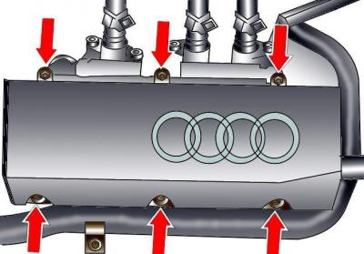
Fig. 3.1–82. Location of the left cylinder head cover mounting bolts
Remove the bolts and remove the cylinder head cover (see Fig. 3.1–82).
Remove the oil deflector.
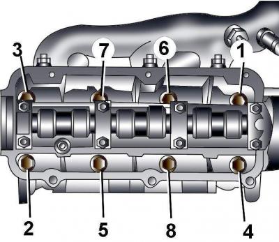
Fig. 3.1–84. Sequence of tightening the bolts for fastening the left and right cylinder heads
In the reverse order of tightening, gradually loosen and then completely unscrew the cylinder head mounting bolts (Fig. 3.1–84).
Remove the cylinder head and place it on a soft surface.
Preparing the left head for installation
The mating surfaces of the cylinder head and block must be completely clean. Use a hard plastic or wooden scraper to clean them. Be careful when cleaning, as the aluminum alloy is very easy to damage. Make sure that carbon deposits do not get into the channels of the lubrication and cooling systems. This is especially important for the lubrication system, as carbon deposits can block the supply of oil to engine parts. Clean the channels if necessary.
Check the mating surfaces of the cylinder head and block: there should be no nicks, deep scratches or other damage. Minor defects can be eliminated by mechanical treatment. In case of significant defects, the parts are subject to replacement.
Using a metal ruler and feeler gauge, check the flatness of the mating surfaces.
If the deviation from flatness exceeds 0.1 mm, it is necessary to regrind the head. Cylinder head height
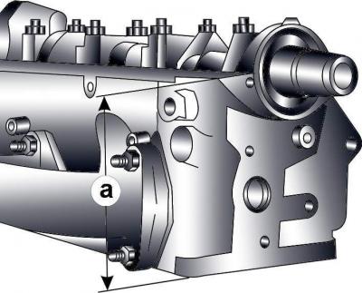
Fig. 3.1–85. Cylinder head height measurement location
a (Fig. 3.1–85) after mechanical processing should be at least 132.75 mm for a six-cylinder engine.
Clean the bolt holes in the block. Driving a bolt into an oil filled hole can cause the block to burst due to hydraulic pressure.
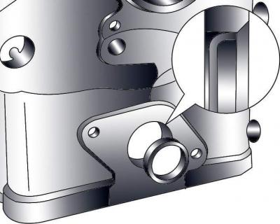
Fig. 3.1–86. Location of the plug in the front end of the cylinder head
The cylinder head supplied as spare parts can be used on either the left or right side. In this case, the plug in the end of the head must be located on the front side of the head (Fig. 3.1–86). When installing the plug, apply AMW 188 001 02 sealant to its outer surface. Install the plug flush with the end of the cylinder head.
Installation
Installation is carried out in the reverse order of removal, taking into account the following.
Replace the cylinder head bolts.
When installing the cylinder head, it is necessary to replace the self-locking nuts and bolts, which were tightened by turning them to a certain angle, with new ones, as well as the sealing rings and gaskets.
The new cylinder head gasket must be removed from the packaging immediately prior to installation.
Place the gasket on the guide pins with the "oben" lettering facing the head.
If work has been done on the valve train, rotate the crankshaft manually two full revolutions to ensure that the pistons have not hit the valves.
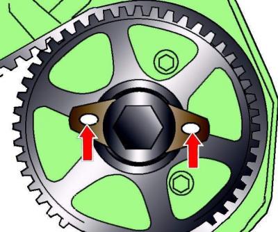
Fig. 3.1–52. Location of large holes of locking plates on camshaft pulleys
Before installing the cylinder head, set the piston of the first cylinder and the camshaft to TDC in the compression stroke. In this case, the large holes of the locking plates on the camshaft pulleys should be directed towards each other (see Fig. 3.1–52).
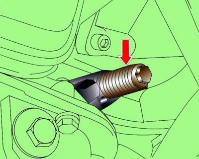
Fig. 3.1–53. Location of the 3242 set screw for fixing the crankshaft
Fix the crankshaft in this position by unscrewing the ignition timing sensor from the cylinder block and screwing in the set screw 3242 instead (see Fig. 3.1–53).
Insert the cylinder head mounting bolts and tighten them by hand.
In the sequence shown in Figure 3.1–84, tighten the cylinder head mounting bolts in two stages:
- 1st - tighten to 60 Nm;
- 2nd - turn it by 180°.
Further tightening of the cylinder head mounting bolts is not required.
Install intake manifold.
Install the timing belt and adjust its tension.
Install the poly V-belt.
Install the exhaust pipe and check that the exhaust system components are installed correctly.
Fill with coolant.
Connect the ground wire to the battery.
Turn on the radio and enter the code into it.
Raise the power windows all the way up. Then press all the power window switches again for at least 1 second to the closed position to activate the power window control unit.
Set the time on the clock.
Right cylinder head
Removal
Set the piston of the first cylinder to TDC in the compression stroke.
Make sure the engine is cold. If not, let it cool down.
Turn off the ignition and remove the ground wire from the battery.
Drain the coolant from the engine cooling system.
Remove the right exhaust pipe.
Remove the timing belt from the pulleys.
Remove the rear timing belt cover.
Take it off intake manifold.
Loosen the power steering pipe bracket mounting bolt.
Mark the high-voltage wires with numbers, remove them from the spark plugs of cylinders 1–3 and move them to the side.
Loosen the clamp, remove the hose from the cooling system pipe and unscrew the bolt securing the pipe to the left cylinder head.
Loosen the coolant pipe flange mounting bolts to the rear of the cylinder head while supporting the pipe.
Fig. 3.1–87. Location of the engine oil level indicator (dipstick) guide tube mounting bolt
Loosen the bolt securing the engine oil level indicator (dipstick) guide pipe on the cylinder head and pull the pipe upwards (Fig. 3.1–87).
Disconnect all electrical connectors from the cylinder head and move them to the side.
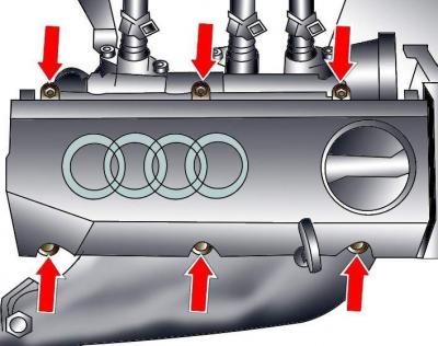
Fig. 3.1–83. Location of the right cylinder head cover mounting bolts
Remove the bolts and cylinder head cover (see Fig. 3.1–83).
Remove the oil deflector.
In the reverse order of tightening, gradually loosen and then completely unscrew the cylinder head mounting bolts (see Fig. 3.1–84).
Remove the cylinder head and place it on a soft surface.
Preparing the head for installation
See "Preparing the Left Head for Installation".
Installation
Installation is carried out in the reverse order of removal, taking into account the following.
Replace the cylinder head bolts.
When installing the engine, it is necessary to replace the self-locking nuts and bolts, which were tightened by turning them to a certain angle, with new ones, as well as the sealing rings and gaskets.
The new cylinder head gasket must be removed from the packaging immediately prior to installation.
Place the gasket on the guide pins with the "oben" lettering facing the head.
If work has been done on the valve train, manually rotate the engine crankshaft two full revolutions to ensure that the pistons have not hit the valves.
Before installing the cylinder head, set the piston of the first cylinder and the camshaft to TDC in the compression stroke. In this case, the large holes of the locking plates on the camshaft pulleys must be directed towards each other (see Fig. 3.1–52).
Fix the crankshaft in this position by unscrewing the ignition timing sensor from the cylinder block and screwing in the set screw 3242 instead (see Fig. 3.1–53).
Insert the cylinder head mounting bolts and tighten them by hand.
In the sequence shown in Figure 3.1–84, tighten the cylinder head mounting bolts in two stages:
- 1st - tighten to 60 Nm;
- 2nd - turn it by 180°.
Further tightening of the cylinder head mounting bolts is not required.
Install intake manifold.
When installing the guide tube for the oil level indicator (dipstick), install the sealing ring.
Install the timing belt and adjust its tension.
Install the poly V-belt.
Install the exhaust manifold.
Fill the cooling system with coolant.
Connect the ground wire to the battery.
Turn on radio and enter the code into it.
Raise the power windows all the way up. Then press all power window switches again for at least 1 second to the closed position to activate the power window control unit.
Set the time on the clock.
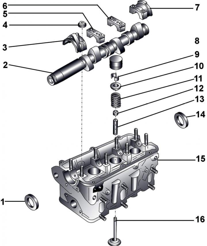
Fig. 3.1–88. Details of the left cylinder head of a six-cylinder engine: 1 – sealing ring; 2 – camshaft; 3 – bearing cover No.1; 4 – nut, 20 Nm; 5 – bearing cover No.2; 6 – bearing cover No.3; 7 – bearing cover No.4; 8 – hydraulic pusher; 9 – crackers; 10 – upper valve spring plate; 11 – valve spring; 12 – oil deflector cap; 13 – valve guide bushing; 14 – sealing ring; 15 – cylinder head; 16 – valve