
Turn the crankshaft and set the pistons of the first cylinder to the bottom dead center position (NMT).
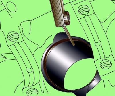
If a shoulder has formed in the upper part of the cylinder, then it must be removed with a reamer or scraper without damaging the cylinder wall. The formation of a shoulder indicates increased wear on the cylinder.
Loosen the cylinder 1 connecting rod cap bolts. Remove the cover and remove the lower connecting rod bearing. If the insert is to be installed again, tape it to the removed cover.
Use a hammer handle to push the piston into the cylinder and remove it through the top of the cylinder block. Remove the upper connecting rod bearing and tape it to the removed connecting rod.
Place the cover on the connecting rod and secure with bolts to maintain the previous order of assembly of the parts.
After repeating the above operations, remove the connecting rods with pistons in the remaining cylinders.
Before checking pistons with connecting rods, remove the piston rings from the pistons and thoroughly clean the pistons.
To remove the piston rings from the pistons, open the ring and insert two or three old feeler blades evenly around the circumference under it and slide the ring off the piston along them. Be careful not to scratch the piston with the ends of the ring. Rings are very brittle and can crack if unclenched too much. Handle the sharp working edges of the piston rings with care to avoid cuts. Keep each set of rings with the pistons to reinstall them.
Clean all carbon deposits from the top of the piston.
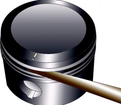
Remove carbon deposits from the piston ring grooves using the old piston ring.
After removing deposits, clean the piston with connecting rod with a suitable solvent and wipe dry.
Carefully inspect each piston for cracks around the skirt and piston pin holes.
Check for wear on the piston skirt, bores in the piston head, and for burnout at the top of the piston.
Pitting marks on the piston indicate that coolant has entered the combustion chamber. It is necessary to find out the cause of fluid entering the combustion chamber and eliminate it.
Determine the clearance of the piston in the cylinder, equal to half the difference between the diameters of the cylinder and piston.
Check each connecting rod for wear, cracks, and distortion.
Connecting rods usually do not require replacement unless the engine is stuck.
When installing, do the following.
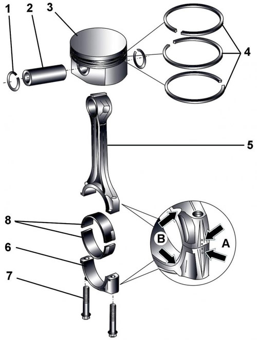
Pic. 3.1–74. Piston and connecting rod: 1 - retaining ring; 2 - piston pin; 3 - piston; 4 – piston rings; 5 - connecting rod; 6 - connecting rod cover; 7 - bolt, 30 Nm + tighten by 90°; 8 - connecting rod bearings
Before installing piston pin 2 (pic. 3.1–74) it is necessary to heat the piston 3 to a temperature of 60°C.
Note the mounting position of the piston and the number of the cylinder in which it is installed.
The arrow on the piston crown points to the belt pulley.
Before installing the piston in the cylinder, the piston rings must be compressed with a band clamp.
Measure the piston diameter.
Piston ring locks are located at an angle of 120°.
Label «TOP» on the piston ring must point towards the piston crown.
Measure the clearance in the piston ring lock.
Check clearance between piston ring and piston groove.
Identification marks are applied to the connecting rod and connecting rod cap A, which should be located on one side.
Identification lugs are made on the connecting rod and the connecting rod capIN, defining the mounting position of the connecting rod. On cylinders 1-3, the identification lugs should be on the pulley side, and on cylinders 4-6, on the flywheel side.
When installing it is necessary to use new bolts 7.
Before screwing in the bolts, the threads and the bearing surface of the bolt heads must be lubricated with oil.
When installing, the correct mounting position of the connecting rod bearing must be observed.
Checking the clearance in the piston ring lock
Pic. 3.1–75. Using a feeler gauge to measure the piston ring gap
Insert the ring into the corresponding cylinder and push the piston head to a depth of 15 mm to prevent distortion of the ring during measurement, then remove the piston. Measure the clearance with a feeler gauge (pic. 3.1–75). If the gap exceeds the norm, then replace the rings and repeat the procedure.
If the gap is too small (which is unlikely), it is best to pick up new rings with a standard gap in the lock. Otherwise, serious damage will occur due to the closing of the rings during engine operation. In extreme cases, the gap can be increased by carefully filing the ends of the ring lock with a thin file. To do this, clamp the needle file in a vise with soft jaws, insert the ring so that the ends of the lock are on both sides of the file, and, slowly moving the ring, remove excess material. Keep in mind that the ring is very fragile and can break easily.
Checking the clearance between piston rings and piston grooves
Pic. 3.1–76. Using a feeler gauge to measure the clearance between the piston ring and the piston groove wall
Check clearance between piston ring and piston groove wall. To do this, insert the ring from the outside into the corresponding groove and use a feeler gauge to measure the gap between the upper surface of the ring and the groove wall (pic. 3.1–76). If the gap exceeds the limit when installing a new ring, replace the piston.
Piston diameter measurement
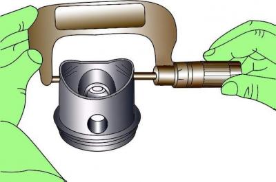
Pic. 3.1–77. Using a micrometer to measure the piston diameter
Measure the piston diameter with a micrometer in a plane perpendicular to the axis of the piston pin, at a distance of 10 mm from the bottom edge of the piston skirt (pic. 3.1–77). The measured value must differ from the nominal value by no more than 0.04 mm. If the piston wear exceeds the maximum allowable value, the piston must be replaced.
Cylinder diameter measurement
The cylinder diameter is measured in three planes in the transverse and longitudinal directions (pic. 3.1–78). The clearance between the piston and the cylinder is defined as the difference between the measured diameters of the cylinder and the piston.
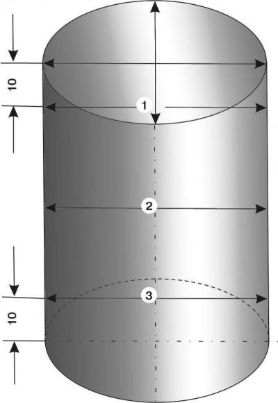
Pic. 3.1–78. Cylinder diameter measuring points
The deviation of the cylinder diameter from the nominal value should not exceed 0.08 mm.
Pistons
Using a waterproof marker, mark the piston crowns with identification marks. The arrow on the piston crown points to the belt pulley.
Connecting rod
Connecting rods do not need to be replaced except in the event of an engine seizure or other major failure. Check the condition of the connecting rods visually, take the deformed connecting rods to a service station for inspection and repair by an experienced specialist.
The connecting rod can only be replaced together with the connecting rod cap.
When removing the connecting rod bearings, be sure to install them in their original places.
Before removal, check for identification marks on the connecting rod and connecting rod cap. Mark the connecting rod caps with the numbers of the respective cylinders in which they are installed.
The radial clearance of the connecting rod is checked in the same way as the radial clearance in the main bearings of the crankshaft, using a plastic Plastigage rod.
Warning: After unscrewing the intake manifold bolts, all cylinder head bolts must be re-tightened by turning 90°further.
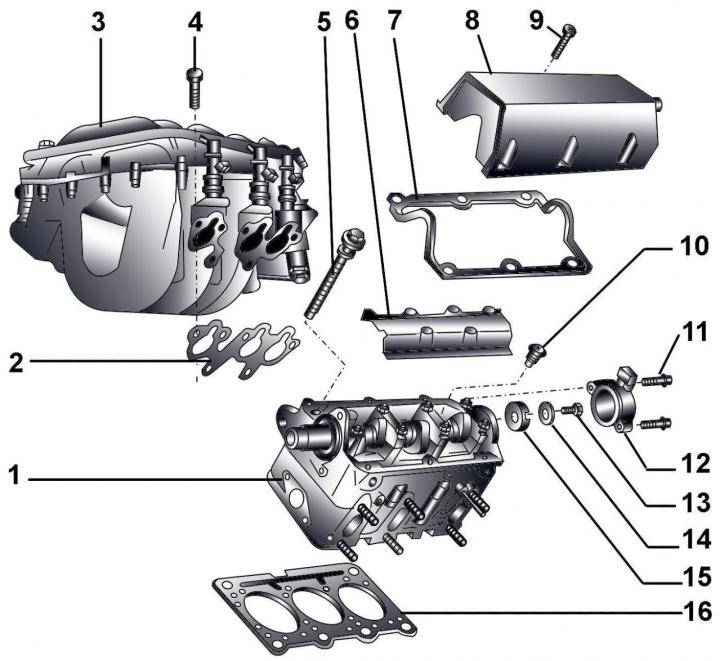
Pic. 3.1–79. Cylinder head: 1 – a head of the block of cylinders; 2 - gasket; 3 - intake manifold; 4 - bolt, 20 Nm; 5 – bolts of fastening of a head of the block of cylinders; 6 - oil deflector; 7 – laying of a cover of a head of the block of cylinders; 8 – a cover of a head of the block of cylinders; 9 - bolt, 10 Nm; 10 - pressure limiting valve 2.7 bar, 25 Nm; 11 - bolt, 10 Nm; 12 - casing; 13 - bolt, 22 Nm; 14 - conical washer; 15 - rotor; 16 – laying of a head of the block of cylinders
Visitor comments