
Table of contents: Removal ↓ Installation ↓
The poly V-belt drives the generator, power steering pump, radiator fan, air conditioning compressor and water pump, depending on the engine modification.
Removal
When removing the poly V-belt, the following must be taken into account.
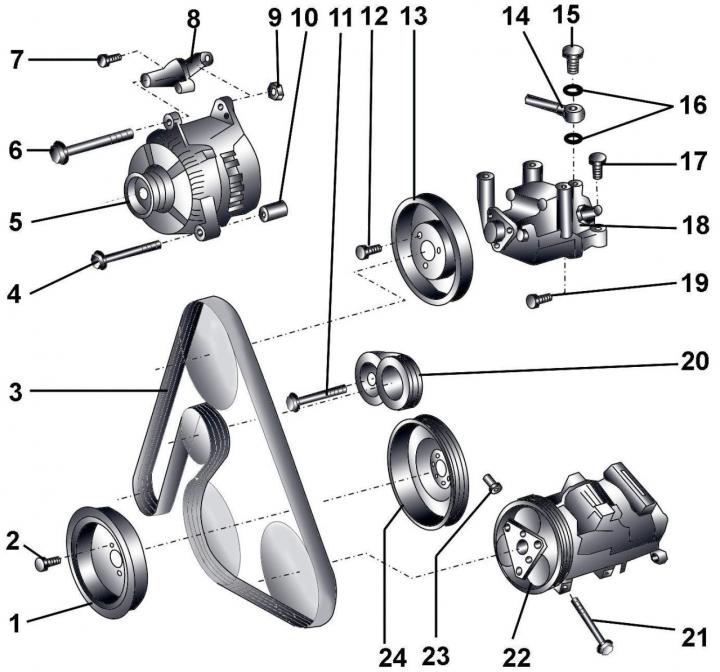
Fig. 3.1–39. Units driven by a poly V-belt: 1 – vibration damper; 2 – bolt, 22 Nm; 3 – poly V-belt; 4 – bolt, 22 Nm; 5 – generator; 6 – bolt, 45 Nm;7 – bolt, 22 Nm; 8 – generator bracket; 9 – bolt, 45 Nm; 10 – spacer sleeve; 11 – bolt, 55 Nm; 12 – bolt, 22 Nm; 13 – Power steering pump pulley; 14 – Power steering pressure line; 15 – hollow bolt, 40 Nm; 16 – sealing rings; 17 – bolt, 22 Nm; 18 – Power steering pump with bracket; 19 – bolt, 22 Nm; 20 – Poly V-belt tensioning mechanism; 21 – bolt, 25 Nm; 22 – air conditioning compressor; 23 – special nut, 25 Nm; 24 – poly V-belt pulley
1. When removing and installing pulley 13 (Fig. 3.1–39), special tool 3212 must be used to prevent it from turning.
2. When installing, it is necessary to use a new sealing ring 16.
3. Categorically prohibited unscrew and disconnect the refrigerant lines.
4. When removing the engine, the air conditioner compressor 22 must be moved to the side together with the refrigerant pipes connected to it and secured to the body with soft wire.
5. Installation of pulley 24 is possible only in one position.
Disconnect the ground cable from the battery.
Unscrew the radiator fan shroud and remove it.
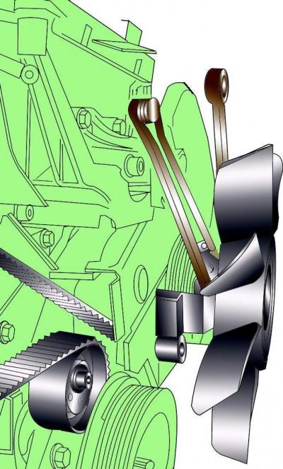
Fig. 3.1–40. Removing the radiator fan mounting bolt
While holding the radiator fan pulley from turning with a special key 3212, unscrew the pulley mounting bolt with a regular key. Since the bolt has a left-hand thread, it must be turned clockwise to unscrew (Fig. 3.1–40).
Lift the radiator fan up and remove it from the vehicle.
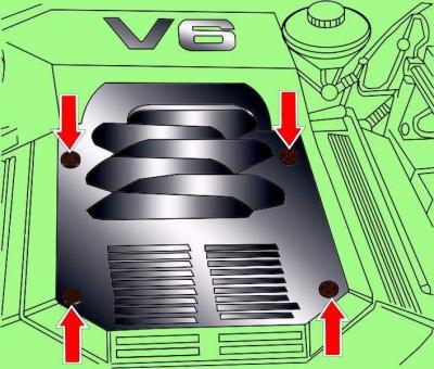
Fig. 3.1–41. Location of engine casing mounting screws
Remove the four screws and remove the engine cover (Fig. 3.1–41).
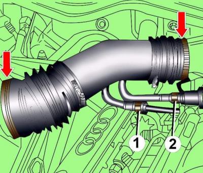
Fig. 3.1–42. Location of the clamps for fastening the air flow meter air pipe and the intake pipe: 1 – fuel supply pipe; 2 – fuel supply hose
Loosen the clamps shown by the arrows in Fig. 3.1–42 and remove the air pipe connecting the air flow meter and the intake pipe.
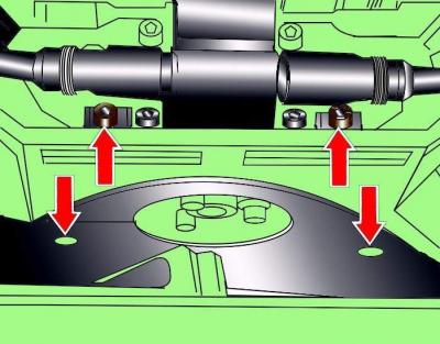
Fig. 3.1–43. Location of the poly V-belt cover mounting screws
Loosen the screws and remove the poly V-belt cover (Fig. 3.1–43).
Warning: Use chalk, marker or paint to mark the direction of rotation of the poly V-belt. If the poly V-belt rotates in the opposite direction during installation, it will cause damage to the belt.
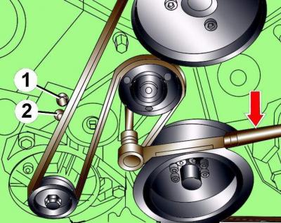
Fig. 3.1–44. Releasing the tension of the poly V-belt: 1, 2 – locations of the pins for fixing the tensioning mechanism. The arrow shows the direction of rotation of the Allen key to reduce the tension of the poly V-belt
Using a 10 mm Allen key, loosen the tension on the poly V-belt by turning the tensioner clockwise until holes 1 and 2 are aligned (Fig. 3.1–44).
Fix the tensioning mechanism in this position by inserting a 5 mm diameter steel rod into the hole.
Remove the poly V-belt from the pulleys.
Installation
Place the drive belt, working counterclockwise, first onto the crankshaft pulley and then onto the tension roller.
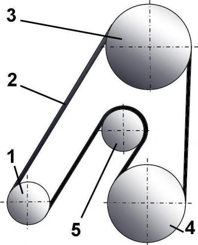
Fig. 3.1–45. Location of the poly V-belt on the pulleys of vehicles without a fan with a viscous clutch and without air conditioning: 1 – generator; 2 – poly V-belt; 3 – Power steering pump; 4 – crankshaft; 5 – belt tension roller
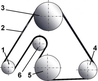
Fig. 3.1–46. Location of the poly V-belt on the pulleys of vehicles equipped with air conditioning, without a fan with a viscous clutch: 1 – generator; 2 – poly V-belt; 3 – Power steering pump; 4 – air conditioning compressor; 5 – crankshaft; 6 – tension roller
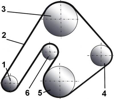
Fig. 3.1–47. Location of the poly V-belt on the pulleys of vehicles with a viscous coupling fan without air conditioning: 1 – generator; 2 – poly V-belt; 3 – Power steering pump; 4 – fan with viscous coupling; 5 – crankshaft; 6 – tension roller
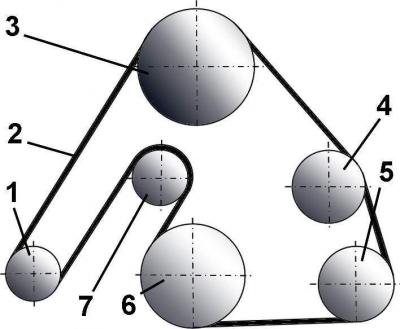
Fig. 3.1–48. Location of the poly V-belt on the pulleys of vehicles with a viscous clutch fan and air conditioning: 1 – generator; 2 – poly V-belt; 3 – Power steering pump; 4 – fan with viscous coupling; 5 – air conditioning compressor; 6 – crankshaft; 7 – tension roller
When installing the poly V-belt, pay attention to its correct position on the pulleys (Fig. 3.1–45, 3.1–46, 3.1–47, 3.1–48).
Remove the steel rod that secures the tensioning mechanism.
Install the radiator fan pulley and secure it with the nut, tightening it to a torque of 37 N·m.
Warning: The radiator fan pulley retaining nut has a left-hand thread and must be tightened by turning it counterclockwise.
Start the engine, check the correct and uniform movement of the poly V-belt.