
Recommendations for engine removal
Please read this section carefully before you begin.
If the engine is removed for repair, it is necessary to select a place for the work, provide space for maintenance and storage of spare parts. It is recommended to carry out repairs at a service station or in a garage with a level horizontal floor with a clean hard surface.
Before removing, clean and wash the engine and engine compartment. To remove the engine, use a lifting mechanism that allows you to safely lift the power unit.
If you are removing the engine for the first time, you should invite an experienced specialist. Some work should be done with an assistant.
All clamps and collars that are damaged or cut during engine removal are replaced with new ones during engine assembly.
The engine is removed forward without the gearbox.
The drained coolant must be collected and disposed of.
Before disconnecting the battery, find out if you have a radio activation code.
Removal
Turn off the ignition and disconnect the ground wire from the battery.
Remove the expansion tank cap.
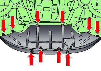
Fig. 3.1–1. Location of the engine compartment lower mudguard mounting fasteners
Release the fasteners shown by the arrows in Fig. 3.1–1 and remove the lower engine compartment splash guard.
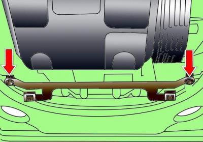
Fig. 3.1–2. Location of engine compartment lower mudguard bracket mounting bolts
Loosen the two bolts and remove the engine compartment lower mudguard bracket (Fig. 3.1–2)
Place a drip pan under the engine to collect the coolant.
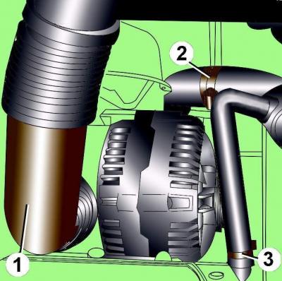
Fig. 3.1–3. Location of the air duct (1) and clamps (2 and 3) for fastening the cooling system hoses
Loosen clamp 3 (Fig. 3.1–3), remove the hose and drain the coolant into the pan.
Loosen clamp 2, remove the hose, move it down and drain the coolant from the radiator.
Disconnect the air duct 1 mount from the generator.
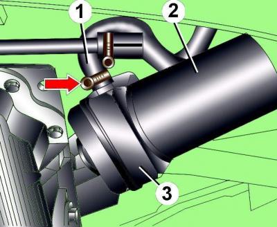
Fig. 3.1–4. Location of oil filter and oil heat exchanger: 1 – hose; 2 – oil filter; 3 – oil heat exchanger
Disconnect the additional coolant hose at the bottom of the oil cooler and drain the coolant into the pan. In Fig. 3.1–4, the arrow shows the clamp securing the additional coolant hose to the oil cooler.
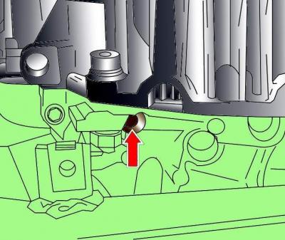
Fig. 3.1–5. Location of the coolant drain plug from the engine cylinder block
Remove the coolant drain plug from the engine cylinder block, shown by the arrow in Fig. 3.1–5.
When installing the plug, a new sealing ring must be used.
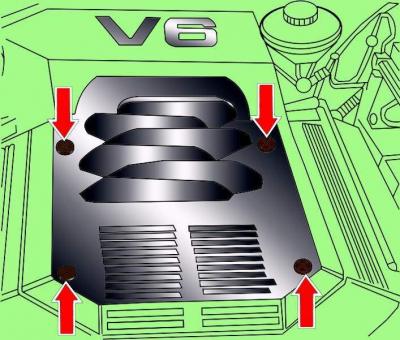
Fig. 3.1–41. Location of engine casing mounting screws
Remove the four screws and remove the engine cover (see Fig. 3.1–41).
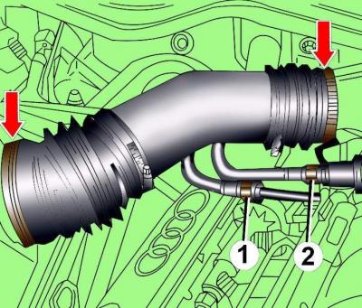
Fig. 3.1–42. Location of the clamps for fastening the air flow meter air pipe and the intake pipe: 1 – fuel supply pipe; 2 – fuel supply hose
Loosen the clamps and remove the air pipe connecting the air flow meter and the intake pipe (see Fig. 3.1–42).
Warning: The fuel system is under pressure. Before disconnecting any fuel system components, relieve the pressure in the system. To do this, cover the fuel system disconnection point with a clean rag and carefully unscrew the union nut smoothly.
Unscrew the nuts and disconnect the fuel supply hose from the pipeline (see Fig. 3.1–42).
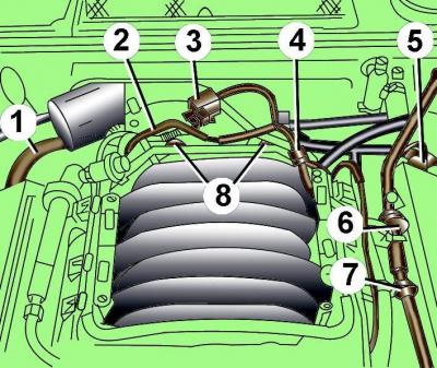
Fig. 3.1–6. Location of hoses in the upper part of the engine: 1 – crankcase ventilation hose; 2, 4, 6, 7 – vacuum hoses; 3 – valve for switching the suction pipeline; 5 – connection of the vacuum hose to the brake booster; 8 – screws for fastening the air pipe of the throttle assembly
Disconnect the crankcase ventilation hose from the right cylinder head cover (Fig. 3.1–6).
Turn out valve 3 to switch the suction pipeline and move it together with the pipeline to the side.
Carefully remove vacuum hose 6.
Unscrew screws 8 and remove the air pipe from the throttle body.
Disconnect the crankcase ventilation hose from the left cylinder head cover.
Remove the brake booster hose from the connector and remove the connector from the bracket.
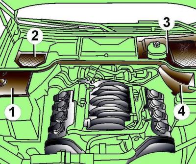
Fig. 3.1–7. Location of protective covers (1–4) in the rear of the engine compartment
Remove protective covers 1–4 at the rear of the engine compartment (Fig. 3.1–7).
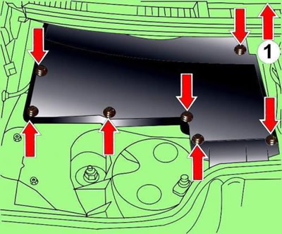
Fig. 3.1–8. Location of screws and direction of removal (1) of the control unit casing
Turn the left cover covering the control unit in the direction indicated by the arrow (1, Fig. 3.1–8) and remove the rear right screw.
Remove the remaining mounting screws shown by the arrows in Fig. 3.1–8.
Remove the control unit cover.
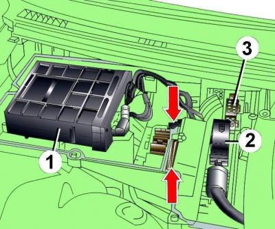
Fig. 3.1–9. Location of the engine control unit (1), drive control unit (2) and electrical connectors (3) on the engine compartment bulkhead
Disconnect the electrical connectors from the engine control unit 1 (Fig. 3.1–9) and the drive control unit 2, as well as all electrical connectors on the engine compartment bulkhead. The arrows indicate the location of the fuse box mounting screws.
Disconnect the electrical connector from the GRA control unit.
Remove the sealing plate located between the engine compartment and the radiator tank.
Release the electrical wiring from the clamps in the engine compartment.
Unscrew the bushings securing the electrical wiring to the engine compartment bulkhead and move the electrical wiring to the side.
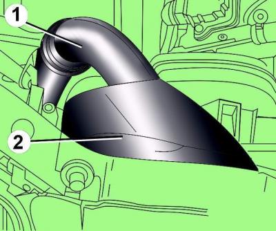
Fig. 3.1–10. Location of the air duct (1) and air intake (2) near the front engine crossmember
Separate air intake 2 (Fig. 3.1–10) from the front crossmember and remove it together with air pipe 1.
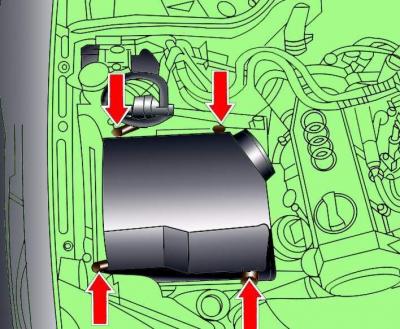
Fig. 3.1–11. Location of screws securing the upper part of the air filter housing
Remove the four screws shown by the arrows in Fig. 3.1–11 securing the upper part of the air filter housing, while disconnecting electrical connectors 1–3 and moving them to the side.
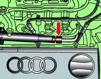
Fig. 3.1–12. Location of the connecting nut for fastening the discharge pipe of the hydraulic pump
Unscrew the union nut and disconnect the hydraulic pump discharge line (Fig. 3.1–12).
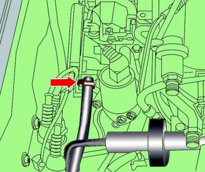
Fig. 3.1–13. Location of the clamp securing the vacuum hose to the AKF valve
Loosen the clamp and disconnect the vacuum hose from the AKF valve (Fig. 3.1–13).
Cars with GRA
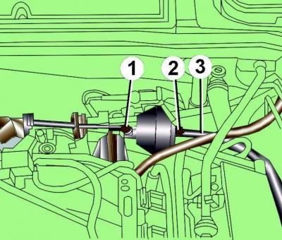
Fig. 3.1–14. Location of control rod (1), vacuum block mounting nut (2) and vacuum hose (3)
Disconnect control rod 1 (Fig. 3.1–14) from the vacuum block.
Remove vacuum hose 3 from the vacuum block.
Unscrew nut 2 and remove the vacuum block.
All cars
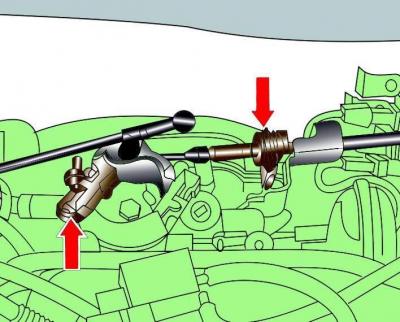
Fig. 3.1–15. Accelerator cable attachment points to the throttle valve and accelerator cable casing to the bracket
Disconnect the accelerator cable from the throttle valve and remove the cable housing from the bracket (Fig. 3.1–15).
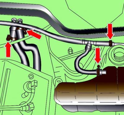
Fig. 3.1–16. Location of clamps for fastening the cooling system hoses to the expansion tank (arrows on the right) and to the heater fittings (arrows on the left) on the engine compartment bulkhead
Loosen the clamps and disconnect the hoses connecting the middle pipe of the cooling system and the expansion tank (arrows on the right in Fig. 3.1–16).
Loosen the clamps (arrows on the left) and disconnect the cooling system hoses going to the heater.
Move the hoses to the lower right side of the engine compartment.
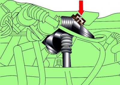
Fig. 3.1–17. Direction of movement of the electrical connector lock
Disconnect all electrical connectors on the front wall by moving the lock in the direction of the arrow (Fig. 3.1–17).
Disconnect the electrical connectors of the lambda sensors and remove the wires going to the lambda sensors from the clips.
Release all engine electrical wiring from the clips.
Cars with manual transmission
Disconnect the electrical connector from the speedometer sensor (arrow A in Fig. 3.1–18).
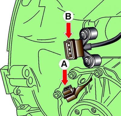
Fig. 3.1–18. Location of electrical connectors for the speedometer sensor (A) and reverse switch (B)
Disconnect the electrical connector from the reverse switch - multifunction sensor (arrow IN).
All cars
Unscrew the exhaust manifold and exhaust pipe mounting nuts accessible from above.
Remove, but not completely, the upper bolts securing the gearbox to the engine.
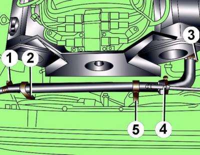
Fig. 3.1–19. Fastening elements of the middle pipe of the cooling system: 1, 3 – clamps; 2, 5 – bolts; 4 – hose
Remove the middle pipe of the cooling system by loosening clamps 1 and 3 (Fig. 3.1–19), unscrewing mounting bolts 2 and 5 and disconnecting hose 4 from it.
Cars with electric radiator fan
Remove the screws, remove the electric radiator fan and set it aside with the connected wires.
Cars with a viscous coupling radiator fan
Unscrew the fan shroud and remove it.
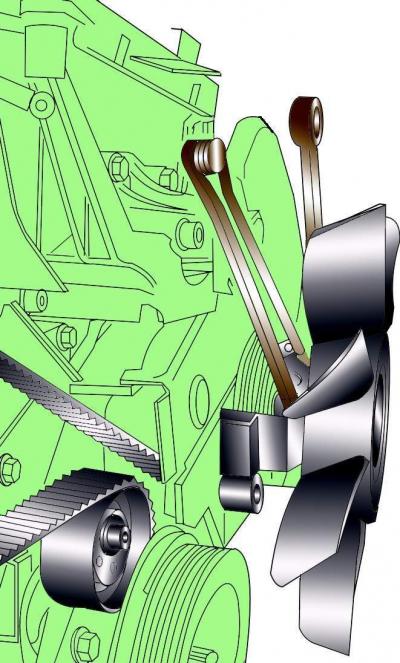
Fig. 3.1–40. Removing the radiator fan mounting bolt
While holding the radiator fan pulley from turning with a special key 3212, unscrew the pulley mounting bolt with a regular key. Since the bolt has a left-hand thread, it must be turned clockwise to unscrew (see Fig. 3.1–40).
Lift the radiator fan up and remove it from the vehicle.
All cars
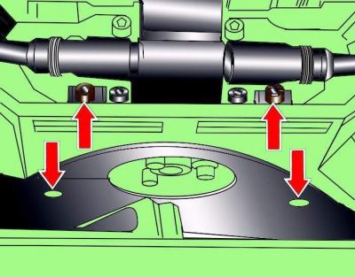
Fig. 3.1–43. Location of the poly V-belt cover mounting screws
Loosen the screws and remove the poly V-belt cover (see Fig. 3.1–43).
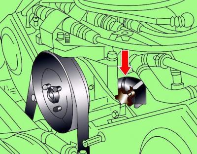
Fig. 3.1–20. Installing the special device (1) for fastening the fuel supply hose to the hydraulic pump
Using the special tool (Fig. 3.1–20), attach the fuel supply hose to the hydraulic pump. At the lower left of the engine compartment, loosen the clamp and unscrew the bolt securing the fuel supply hose bracket.
Move the special tool down between the timing belt cover and the cylinder head or cylinder block.
Place a clean rag under the hydraulic pump to collect any leaking oil.
Cars with manual transmission
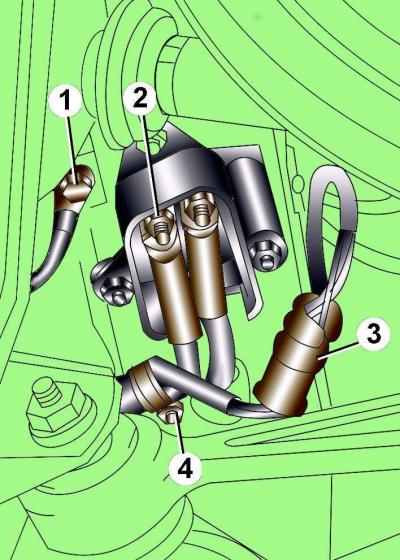
Fig. 3.1–21. Wire and connector fastening elements: 1 – "ground" wire fastening bolt; 2 – wire fastening nut; 3 – electrical connector; 4 – clamp
Release the retainer and disconnect electrical connector 3 (Fig. 3.1–21).
Remove the cover covering the electrical connections.
Unscrew bolt 1 securing the ground wire.
Unscrew the 2 nuts securing the wires.
Unscrew clamp 4 securing the electrical wires and move the wires to the side.
Cars with air conditioning and/or automatic transmission
Warning: Use chalk, marker or paint to mark the direction of rotation of the poly V-belt. If the poly V-belt rotates in the opposite direction during installation, it will cause damage to the belt.
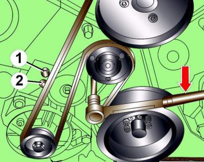
Fig. 3.1–44. Releasing the tension of the poly V-belt: 1, 2 – locations of the pins for fixing the tensioning mechanism. The arrow shows the direction of rotation of the Allen key to reduce the tension of the poly V-belt
Using a 10 mm Allen key, loosen the tension on the poly V-belt by turning the tensioner clockwise until the holes align (arrows 1 and 2, see Fig. 3.1–44).
Fix the tensioning mechanism in this position by inserting a 5 mm diameter steel rod into the holes.
Remove the poly V-belt from the pulleys.
Cars with air conditioning
To collect the oil, place a pan under the engine compartment.
Drain motor oil, unscrewing the oil drain plug and pressing on it if necessary to prevent the oil from leaking out prematurely.
Unscrew the oil filter 2 (see Fig. 3.1–4).
Loosen the clamp and remove the rear hose from the oil cooler.
Remove the oil heat exchanger.
Warning: Do not open the cooling circuit of the air conditioning system.
Remove the air conditioning compressor electrical wires from their mountings.
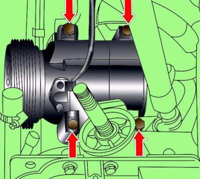
Fig. 3.1–22. Location of air conditioner compressor bracket mounting bolts
Remove the four air conditioning compressor bracket mounting bolts shown by the arrows in Fig. 3.1–22.
Move the air conditioning compressor and any wires and tubes attached to it to the side.
Cars with automatic transmission
Disconnect the electrical wires from the generator.
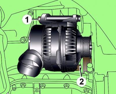
Fig. 3.1–23. Generator fastening elements: 1 – nut; 2 – bolt
Remove the lower bolt 2 (Fig. 3.1–23) securing the generator.
Using a wrench to hold the top bolt from turning, unscrew nut 1.
Remove the upper generator mounting bolt and remove the generator.
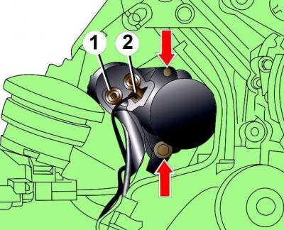
Fig. 3.1–24. Location of starter mounting bolts: 1 – nut; 2 – electrical connector
Disconnect electrical connector 2 (Fig. 3.1–24) from the starter, unscrew nut 1 and disconnect the power ("positive") wire from the starter.
Remove the two bolts (arrows in Fig. 3.1–24) securing the starter and, being careful, remove the starter.
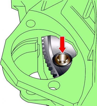
Fig. 3.1–25. Location of torque converter mounting bolt
Through the hole that opens after removing the starter, unscrew the three torque converter mounting bolts (Fig. 3.1–25). To access each subsequent bolt, it is necessary to turn the engine crankshaft in the direction of its working rotation by 1/3 of a turn. To turn the crankshaft, it is necessary to use the central crankshaft pulley mounting bolt.
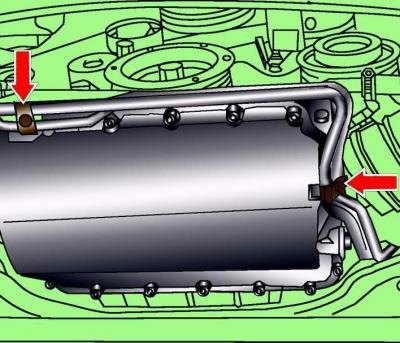
Fig. 3.1–26. Location of bolts for fastening the brackets supporting the pipes to the automatic transmission
Remove the two bolts (Fig. 3.1–26) securing the pipe support brackets to the automatic transmission.
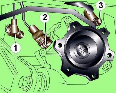
Fig. 3.1–27. Location of engine speed sensor (1), electrical connector (2), speedometer sensor and automatic transmission pipe mounting bolt (3)
If present, unscrew the G28 engine speed sensor 1. Sensor 1 (Fig. 3.1–27) is located in the front left part of the gearbox.
Note: Maintain cleanliness when working on an automatic transmission.
If necessary, remove the automatic transmission and drive shafts.
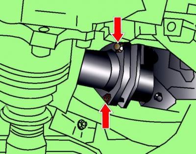
Fig. 3.1–28. Location of nuts securing the exhaust inlet pipe to the front muffler
From underneath the vehicle, unscrew the nuts securing the exhaust inlet pipe to the front muffler (Fig. 3.1–28).
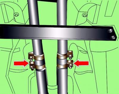
Fig. 3.1–29. Location of exhaust system coupling fastening nuts
Unscrew the nuts indicated by the arrows in Fig. 3.1–29 that secure the connecting sleeves.
Carefully remove the front exhaust pipe with the catalytic converter and lambda sensors, being careful not to damage the wires going to the lambda sensors.
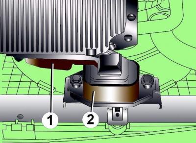
Fig. 3.1–30. Location of the engine torque compensator support: 1 – support; 2 – limiter
Loosen the mounting bolts of support 1 (Fig. 3.1–30) of the engine torque compensator and, moving the support, remove it.
From underneath the vehicle, remove the accessible bolts securing the gearbox to the engine.
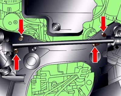
Fig. 3.1–31. Location of engine mounting bolts to the lower frame
Remove the lower bolts (Fig. 3.1–31) securing the engine to the lower frame.
Prepare the left adapter 10-222A/4 and the lifting device 10-222A with clamps to support the gearbox.
On the back side of the upper platform of the 10–222A/4 adapter, drill a hole with a diameter of 10.2 mm and cut an M12 thread.
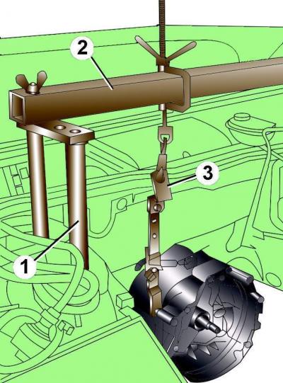
Fig. 3.1–32. Installing gearbox support devices: 1 – left adapter 10-222A/4; 2 - lifting device 10-222A; 3 – set of grips 2024 A/2, 2024 A/1 and 3147
Install the 10–222A/4 adapter and the 10–222A lifting device onto the posts and connect them together using the threaded hole (Fig. 3.1–32).
The lifting screw must be located at the rear of the lifting device.
Secure the lifting device clamp to the gearbox.
Turn the screw of the lifting device to tighten the clamp so that the weight of the gearbox is supported by the lifting device. Completely unscrew the lower bolts securing the gearbox to the engine.
Disconnect the hood support struts from the hood. Position the hood vertically and secure it in this position.

Fig. 3.1–33. Fastening the engine with a lifting clamp 3033: 1 – clamp
Attach lifting clamp 3033 (Fig. 3.1–33) to the hoist and secure it to the engine.
Remove the upper gearbox-to-engine mounting bolts.
Make sure all electrical wires, hoses, pipes and lines are disconnected from the engine.
Cars with automatic transmission
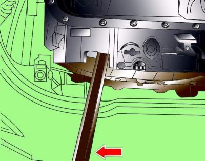
Fig. 3.1–34. Using a pry bar to hold the torque converter against the engine when removing the engine
Before removing the engine, use a crowbar to press the torque converter against the engine (Fig. 3.1–34).
Carefully lift the engine, then move it away from the transmission and lift it up out of the engine bay.
Cars with automatic transmission
Secure the torque converter to the engine.
Installation
The engine is installed in the reverse order of removal, taking into account the following.
Replace with new self-locking nuts and bolts that were tightened by turning to a certain angle, as well as sealing rings and gaskets.
Check for the presence of centering bushings that determine the relative position of the engine and gearbox.
When connecting the engine to the gearbox, be careful not to damage the engine speed sensor.
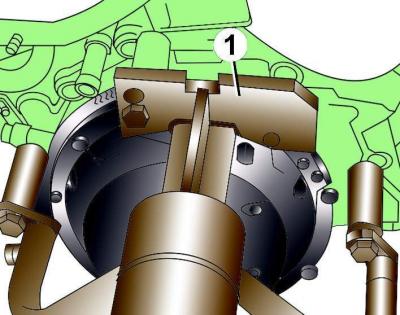
Fig. 3.1–35. Using the special tool VW 540 (1) when installing the engine on the stand
If the engine needs to be repaired, secure it to the stand using the special tool VW 540 (Fig. 3.1–35).
Cars with manual transmission
Clean the drive shaft splines and remove any traces of corrosion from the clutch disc when reusing it. Lubricate the drive shaft splines with a thin layer of G 000 100 grease.
Check the condition of the clutch release bearing and replace it if necessary.
Using a drift, check the centering of the clutch disc.
Check the condition of the needle bearing at the flywheel end of the crankshaft. Replace the bearing if necessary.
Cars with automatic transmission
To attach the torque converter to the drive disk, it is necessary to use bolts of the original design.
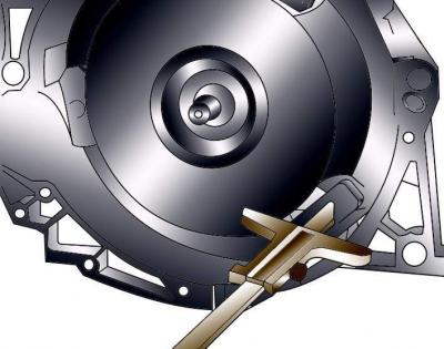
Fig. 3.1–36. Measuring the distance between the bearing surface for the torque converter mounting bolts and the bearing surface of the crankcase
Check the correct installation of the torque converter. If the distance between the supporting surface for the torque converter mounting bolts and the housing surface is 19 mm, then the torque converter is installed correctly. If the torque converter is installed incorrectly, this distance is 14 mm (Fig. 3.1–36). Incorrect installation of the torque converter leads to the destruction of the leading part of the torque converter and the automatic transmission pump.
Place the engine in place and rock it from side to side to ensure it is correctly positioned on the supports.
Install the poly V-belt.
Check that the engine torque compensator support is installed correctly.
If the flywheel was removed, then when installing the engine, move the engine speed sensor to the side.
Check the accelerator cable adjustment.
Fill the cooling system with coolant. Do not reuse coolant if the cylinder head has been removed or the cylinder block has been replaced.
Fill the power steering system with oil and bleed the air from it.
Pour into the engine motor oil.
Make sure that the exhaust system components are properly mounted on the suspensions and do not touch the body when rocking.
Check that the electrical connectors are connected correctly.
Connect the ground wire to the battery.
Turn on the radio and enter the code into it.
Raise the power windows all the way up. Then press all the power window switches again for at least 1 second to the closed position to activate the power window control unit.
Set the time on the clock.
Before starting the engine, check the presence and level of oil in the engine.
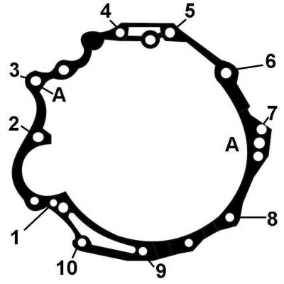
Fig. 3.1–37. Location and numbering of bolts for fastening the manual gearbox to the engine: A – location of installation of the centering sleeve
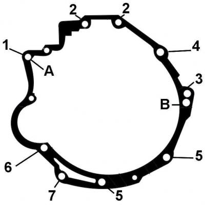
Fig. 3.1–38. Location and numbering of bolts for fastening the automatic transmission to the engine: A, B – locations of installation of centering bushings
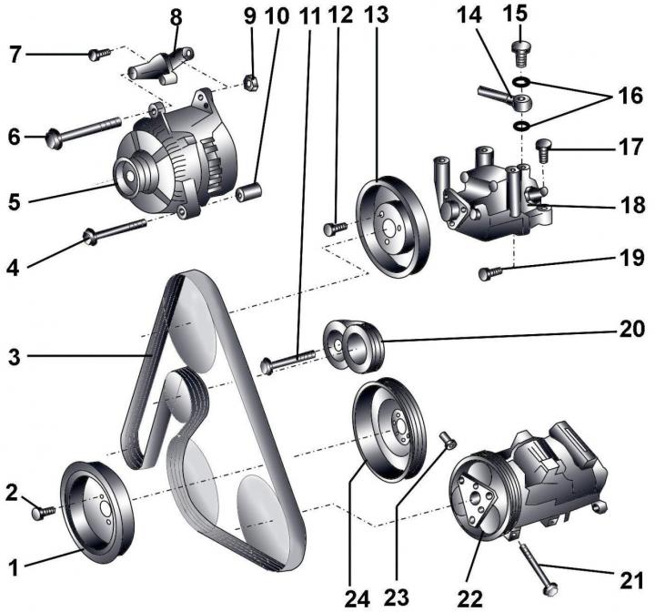
Fig. 3.1–39. Units driven by a poly V-belt: 1 – vibration damper; 2 – bolt, 22 Nm; 3 – poly V-belt; 4 – bolt, 22 Nm; 5 – generator; 6 – bolt, 45 Nm;7 – bolt, 22 Nm; 8 – generator bracket; 9 – bolt, 45 Nm; 10 – spacer sleeve; 11 – bolt, 55 Nm; 12 – bolt, 22 Nm; 13 – Power steering pump pulley; 14 – Power steering pressure line; 15 – hollow bolt, 40 Nm; 16 – sealing rings; 17 – bolt, 22 Nm; 18 – Power steering pump with bracket; 19 – bolt, 22 Nm; 20 – Poly V-belt tensioning mechanism; 21 – bolt, 25 Nm; 22 – air conditioning compressor; 23 – special nut, 25 Nm; 24 – poly V-belt pulley