
Table of contents: Notes ↓ Front Crankshaft Oil Seal ↓
Warning: Before removing, mark the direction of rotation of the timing belt with chalk, marker or paint. If a used timing belt is installed with the opposite direction, it will cause damage to the belt.
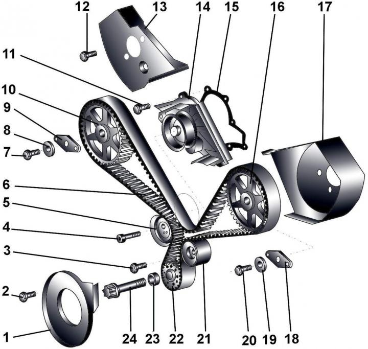
Fig. 3.1–50. Toothed belt: 1 – timing belt cover; 2 – bolt, 10 Nm; 3 – bolt, 43 Nm; 4 – bolt, 22 Nm; 5 – tension roller; 6 – toothed belt; 7 – bolt, 70 Nm; 8 – washer; 9 – fixing plate; 10 – right toothed belt pulley; 11 – bolt, 10 Nm; 12 – bolt, 10 Nm; 13 – rear right timing belt cover; 14 – water pump; 15 – gasket; 16 – left toothed belt pulley; 17 – rear left timing belt cover; 18 – fixing plate; 19 – washer; 20 – bolt, 70 Nm; 21 – guide roller; 22 – crankshaft timing belt pulley; 23 – spacer sleeve; 24 – bolt (200 Nm + turn 180°)
Removing the toothed belt (Fig. 3.1–50.) must be carried out taking into account the following.
1. Check the condition of the timing belt.
2. When installing, it is necessary to use a new bolt 7.
3. Inscription "front vorne" on the fixing plate should be facing forward.
4. When installing, it is necessary to use a new gasket 15 and new bolts 20, 24.
5. There should be no grease on the bearing surface between the toothed belt pulley and the crankshaft. The pulley can only be installed in one position.
6. During installation, do not lubricate bolt 24 with oil.
Remove eight bolts and remove vibration damper.
Remove the poly V-belt.
Remove the poly V-belt tensioner mechanism.
Remove the left and right timing belt covers.
Turning the engine crankshaft in the direction of its working rotation by the pulley mounting bolt, install
the piston of the first cylinder at top dead center (TDC).
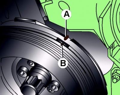
Fig. 3.1–51. Aligning the mark on the crankshaft pulley (B) with the pointer (A) on the casing
Make sure that the mark on the crankshaft pulley is aligned with the pointer on the housing (Fig. 3.1–51).
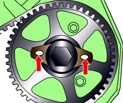
Fig. 3.1–52. Location of large holes of locking plates on camshaft pulleys
Check the position of the camshaft timing belt pulleys. When the piston of the first cylinder is set to TDC in the compression stroke, the large holes of the locking plates on the camshaft pulleys must be directed towards each other (arrow in Fig. 3.1–52). Otherwise, turn the engine crankshaft one revolution.
Remove the lower engine compartment splash shield.
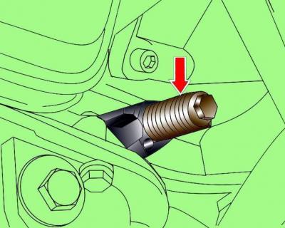
Fig. 3.1–53. Location of the 3242 set screw for fixing the crankshaft
Fix the crankshaft in this position. To fix the crankshaft, unscrew the ignition timing sensor from the cylinder block and screw in the adjusting screw 3242 instead of the sensor (Fig. 3.1–53).
Remove the screws securing the lower part of the timing belt cover.
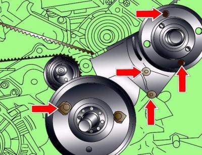
Fig. 3.1–54. Location of radiator fan bracket and lower timing belt housing mounting bolts
Remove the bolts and the radiator fan bracket and the lower timing belt cover (Fig. 3.1–54).
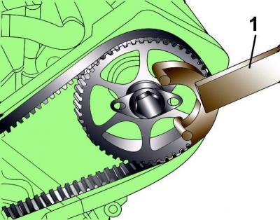
Fig. 3.1–55. Using special tool 3036 (1) to prevent the camshaft pulley from turning
Alternately, using special device 3036 (Fig. 3.1–55), fix the camshaft pulley from turning and unscrew it three turns, but do not completely unscrew the camshaft pulley mounting bolt.
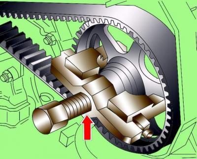
Fig. 3.1–56. Using the T40001 puller (1) to remove the timing belt pulley from the camshaft
Using the T40001 puller (Fig. 3.1–56), remove both camshaft pulleys from their mounting cones. When removing the pulleys, the puller should rest against the camshaft pulley mounting bolts. The camshaft pulleys should rotate freely, but not dangle on the mounting cones.
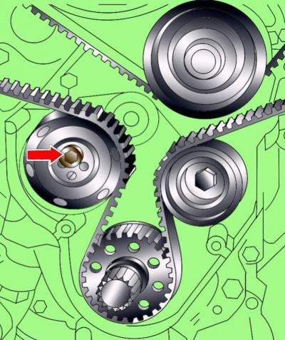
Fig. 3.1–57. Location of the tension roller mounting bolt
Loosen the mounting bolt (Fig. 3.1–57) of the tension roller and loosen the tension of the toothed belt.
Remove the timing belt.
Do not turn the engine crankshaft with the timing belt removed, as the pistons may hit the valves.
Warnings: 1. Do not twist or bend the timing belt. Prevent oil, coolant or fuel from coming into contact with the timing belt.
2. If the timing belt teeth have chipped, the distributor, water pump, oil pump or camshaft may be jammed.
3. A broken timing belt on a running engine can be caused by the pistons hitting the valves, which can cause the valves to become deformed.
4. Check the valve clearances. On deformed valves they will be significantly larger than required.
5. If the outer surface of the timing belt is significantly worn or delaminated, check the condition of the idler pulley raceway.
If wear or damage is found on only one side of the belt, check the timing belt guide and timing belt pulley alignment.
If there are any defects on the timing belt, it must be replaced.
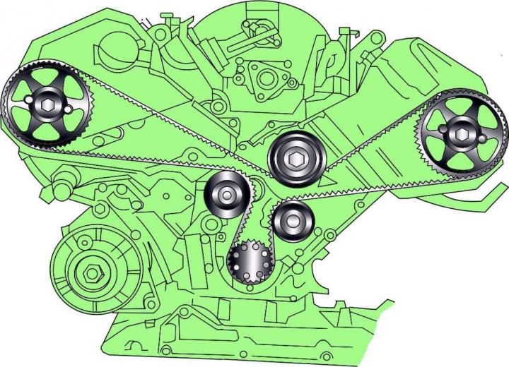
Fig. 3.1–58. Location of the toothed belt on the engine pulleys
6. Install the toothed belt on the engine pulleys, starting with the crankshaft pulley and ending with the tension roller. The previously removed belt is installed in accordance with the marks applied (Fig. 3.1–58).
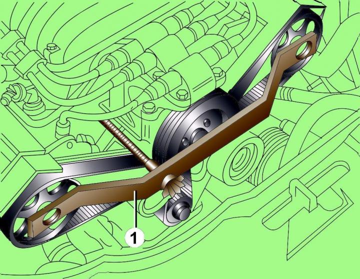
Fig. 3.1–59. Installing the 3243 (1) retainer for the camshaft pulleys
Install special retainer 3243 (Fig. 3.1–59) to hold the camshaft pulleys.
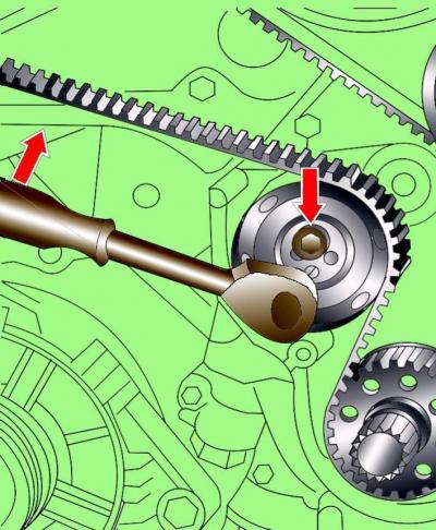
Fig. 3.1–60. Tensioning the toothed belt with the tension roller and the location of the tension roller fixing bolt
Turn the timing belt tensioner roller clockwise with an 8 mm Allen key (Fig. 3.1–60). Tension the timing belt and tighten the tensioner roller mounting bolt with a second 8 mm Allen key to a torque of 22 N·m.
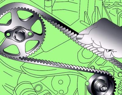
Fig. 3.1–61. Checking the tension of the toothed belt by turning it 90°
Check the tension of the toothed belt in the center of the branch between the right toothed belt pulley and the water pump pulley. The toothed belt should turn 90° with moderate finger pressure (Fig. 3.1–61).
Pre-tighten the camshaft pulley mounting bolts to 30 Nm.
Remove tool 3243, which holds the camshaft pulleys.
Finally tighten the camshaft pulley mounting bolts to a torque of 70 Nm.
Remove the 3242 set screw that holds the engine crankshaft from turning. Screw in the ignition timing sensor with a new sealing ring.
Install the poly V-belt.
Install the radiator fan with viscous coupling.
Notes
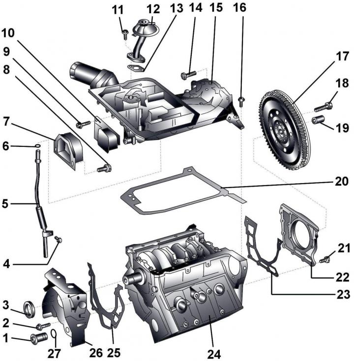
Fig. 3.1–62. Oil pan, front and rear engine covers: 1 – bolt, 30 Nm; 2 – bolt, 10 Nm; 3 – crankshaft sealing ring; 4 – bolt, 10 Nm; 5 – guide tube for oil dipstick indicator; 6 – sealing ring; 7 – limiter for engine torque compensator support; 8 – bolt, 40 Nm; 9 – bolt, 40 Nm; 10 – Engine torque compensator support; 11 – bolt, 10 Nm; 12 – oil receiver with branch pipe; 13 – gasket; 14 – bolt (M8 – 25 Nm, M10 – 45 Nm); 15 – upper part of the oil pan; 16 – bolt, 10 Nm; 17 – dual mass flywheel; 18 – flywheel mounting bolt (60 Nm + turn further by 180°); 19 – needle bearing; 20 – gasket; 21 – bolt, 10 Nm; 22 – back cover with sealing ring, 23 – gasket; 24 – cylinder block; 25 – gasket; 26 – oil pump; 27 – sealing ring
1. When installing, it is necessary to use new sealing rings 6, 27 and gaskets 13, 20, 23, 25 (Fig. 3.1–62).
2. No additional sealing means are required when installing the upper part 15 of the oil pan.
3. The tightening torque of the friction lining mounting bolts for vehicles with automatic transmission is 60 Nm + further tighten by an angle of 90°.
4. Needle bearing 19 is installed only on vehicles with a manual transmission and is pressed into the end of the crankshaft.
5. Before removing the rear cover, the oil pan must be removed.
Front Crankshaft Oil Seal
Remove the timing belt.
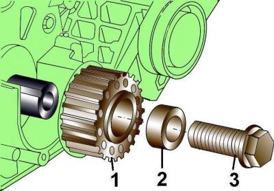
Fig. 3.1–63. Crankshaft pulley fastening elements: 1 – crankshaft toothed belt pulley; 2 – spacer sleeve; 3 – bolt
Remove bolt 3 (Fig. 3.1–63) securing the crankshaft pulley.
Remove spacer sleeve 2 and pulley 1 of the toothed belt.
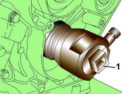
Fig. 3.1–64. Using puller 3203 (1) to remove the front crankshaft seal ring
To remove the front seal ring, use puller 3203 (Fig. 3.1–64). Unscrew the inner part of the puller six turns from the outer part of the puller and firmly fix both parts.
Place the puller on the crankshaft and press it firmly into the sealing ring. Unlock both parts of the puller and, rotating the inner part of the puller, remove the sealing ring. Remove the sealing ring from the puller.
Clean the sealing ring installation area.
Lubricate the sealing lip and outer surface of the new O-ring with engine oil before installing it in place.
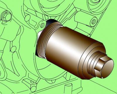
Fig. 3.1–65. Using the 3265 drift to install the front crankshaft oil seal ring
Using drift 3265 (Fig. 3.1–65), install the seal ring onto the crankshaft and press the seal ring into the seat using the pulley mounting bolt.
Install pulley 1 (see Fig. 3.1–63) of the crankshaft toothed belt, spacer sleeve 2 and screw in fastening bolt 3.
Warnings: There must be no grease on the bearing surface between the pulley and the crankshaft. Do not lubricate the crankshaft pulley mounting bolt.
When installing, it is necessary to use a new crankshaft pulley mounting bolt.
Install the timing belt.
[The original material is located on the website: AUDImanual.ru]