
If the crankshaft has been reground, check for burrs around the lubrication holes. Remove any burrs found with a file or scraper and thoroughly clean the holes and passages of chips.
Use a micrometer to measure the diameter of the main and connecting rod journals of the crankshaft and compare the results with the technical data. Measure the journals at several points both in diameter and in length, this will allow you to identify ovality and taper, if any.
Inspect the oil seal contact surfaces at each end of the crankshaft for wear or other damage. If the seal journal is severely worn, the crankshaft may need to be replaced.
Wear of the connecting rod journal is characterized by metallic knocking sounds that occur when the engine is running under load, at low speed, and by a decrease in oil pressure.
Wear of the crankshaft main journals is characterized by strong engine vibration and a metallic knocking sound, which intensifies with increasing engine speed, as well as a decrease in oil pressure.
Even if the main and connecting rod bearings are subject to replacement during a major overhaul of the engine, they must be carefully inspected: their defects can be used to judge the technical condition of the engine.
Bearing failure can be caused by lack of lubrication, dirt and foreign particles, engine overload, or corrosion. The cause of bearing failure must be corrected before the engine is reassembled.
To inspect the bearings, remove them and arrange them in the same order as they were installed on the engine. This will help identify the appropriate crankshaft journal and make troubleshooting easier.
Foreign particles can enter the engine in a variety of ways. Metallic particles appear in the engine oil as a result of normal engine wear. Small particles can enter the bearings along with the engine oil and easily penetrate its soft material. Larger particles, getting into the bearing, can scratch it or the crankshaft journal. To prevent bearing failure due to this reason, it is necessary to thoroughly clean all internal surfaces of the engine and keep them clean during assembly. It is recommended to observe the required frequency of oil and filter changes.
Insufficient lubrication of the crankshaft journals can be caused by many reasons: high oil temperature, engine overload, oil leakage, etc.
Driving style also affects the durability of bearings. With the throttle fully open at low engine crankshaft speeds, the load on the bearings increases and the oil film is squeezed out of the contact zone. High loads lead to cracks in the working part of the bearing, which in turn can cause the antifriction layer to separate from the steel base.
Short-distance driving causes bearing corrosion because the engine does not reach a stable operating temperature, which removes water vapor and corrosive gases. The vapors and gases condense in the engine oil, forming acid and sediment. The acid gets to the bearings along with the engine oil and causes their corrosion.
Incorrect selection of bearings during engine assembly also causes their failure. Bearings installed with preload leave a gap that is insufficient to ensure normal lubrication of the rubbing surfaces.
When installing the crankshaft, the following must be taken into account.
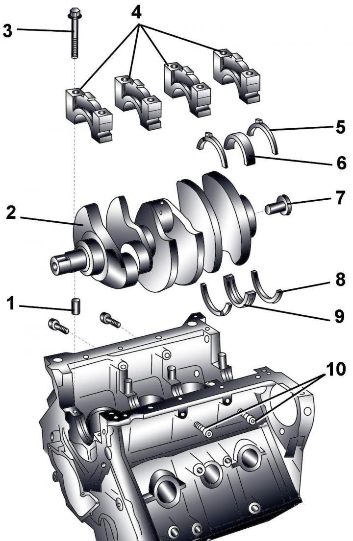
Fig. 3.1–70. Crankshaft: 1 – centering sleeve; 2 – crankshaft; 3 – bearing cap mounting bolts; 4 – bearing caps; 5 – thrust half ring; 6 – main bearing shell; 7 – Bearing bush, used only with automatic transmission; 8 - thrust half ring; 9 - main bearing shell with lubrication groove; 10 – bolts
1. Centering sleeve 1 (Fig. 3.1–70) ensures correct installation of the main bearing caps.
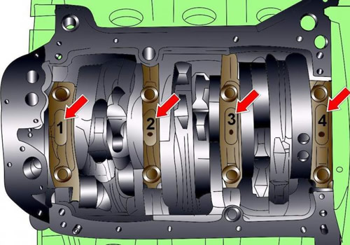
Fig. 3.1–71. Location and numbering of crankshaft main bearings
2. Main bearing No.1 is located on the belt pulley side, and bearing No.4 is located on the flywheel side (Fig. 3.1–71).
3. When installing, it is necessary to use new bolts 3 (see Fig. 3.1–70).
4. Thrust half rings 5 are installed only on main bearing No.4.
The lubrication grooves of the thrust half rings must be directed outward.
Thrust half rings are used to adjust the axial clearance of the crankshaft.
5. The insert without a lubrication groove is installed from the side of the bearing cover.
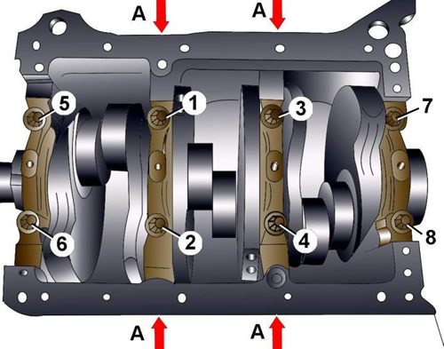
Fig. 3.1–72. Sequence of tightening the main bearing cap bolts
The main bearing cap fastening bolts are tightened in the sequence shown in Figure 3.1–72, in four stages:
- 1st - tighten the side bolts A by hand;
- 2nd - tighten bolts 1–8 to 60 Nm;
- 3rd - tighten bolts 1–8 to an angle of 90°;
- 4th - tighten the side bolts A torque of 25 Nm.
Measuring axial and radial clearances of the crankshaft
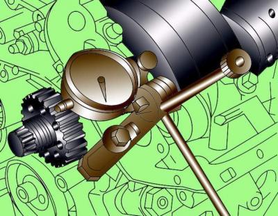
Fig. 3.1–73. Installing a bracket with a dial indicator for measuring the crankshaft axial clearance
Install a bracket with a dial indicator on the engine cylinder block so that the measuring tip of the indicator rests against the crankshaft counterweight (Fig. 3.1–73).
Move the crankshaft along the axis in one direction until it stops and set the indicator to 0. Move the crankshaft along the axis in the other direction until it stops and record the value on the indicator. The nominal value of the crankshaft axial clearance is 0.07–0.23 mm, the maximum permissible value is 0.25 mm.
To measure the radial clearance in the crankshaft bearings, it is necessary to use a calibrated plastic Plastigage rod.
Loosen the bolts and remove the cover and main bearing shell. Clean the shell, cover and crankshaft journal.
Cut a piece of plastic calibrated rod, the length of which is equal to the width of the bearing, and place it along the axis of the crankshaft on the journal of the main bearing.
Install the main bearing cap with the liner and secure it with bolts, tightening it to a torque of 30 N·m. Do not turn the crankshaft.
Loosen the bolts and remove the main bearing cap again. Compare the width of the deformed plastic rod with the measuring scale printed on the plastic rod packaging. Determine the radial clearance using the scale. The nominal value of the crankshaft radial clearance is 0.018–0.045 mm, the maximum permissible value is 0.10 mm.
(Material republished from the website audimanual.ru)