Repair Chevrolet Repair Toyota Repair Honda Repair AvtoVAZ Repair Mercedes-Benz Repair BMW Repair Opel
Home  |  Contacts  |  Sitemap  |    
English Русский
Български
Беларускі
Український
Српски
Hrvatski
Română
Polski
Slovenský
Magyar
AudiManual.ru


  • AUDI 80
  • AUDI 100
  • AUDI A3
  • AUDI A4
  • AUDI A6
  • AUDI A8
  • AUDI Q
  • OTHER
  • ARTICLES
Type 8L (1996-2003)

Checking the crankshaft (Audi A3 8L)

  • Home
  • Audi A3
  • Type 8L (1996-2003)
  • Power unit
  • Engine repair
  • Checking the crankshaft
            0
1. Carefully inspect the crankshaft for damage and take precise measurements of the main and connecting rod bearing journals. The main bearing journals and connecting rod journals can be bored up to three times, so that a shaft with oversize (smaller) bearing shells can be installed. The diameter of the connecting rod journals is the same for all engine types.

2. Clamp the crankshaft between lathe centers (or place the bearing journals in prisms) and using a dial indicator, measure the runout on the middle journal. The runout should not exceed 0.06 mm. Otherwise, the shaft should be replaced.

3. Measure the clearances in the main and connecting rod bearings.

4. Clean the bearing shells thoroughly and place them in the bearing beds of the cylinder block or in the connecting rods.

5. Place a piece of material on each "Plastigage" (plastic "wire") on the journal of each main bearing and on the cap of each main bearing with inserted liners. Tighten the bolts with a tightening torque of 65 Nm. Do not turn the shaft after this.

5. Place a piece of material on each «Plastigage» (plastic «wire») on the journal of each main…


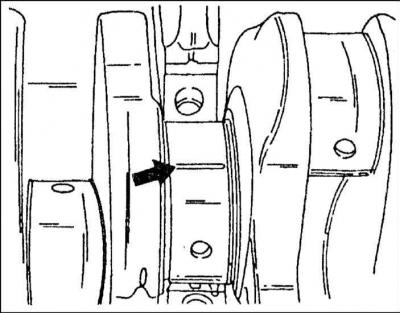
6. To check the clearances of the connecting rod bearings, you need to put the connecting rod to the crank journal and put a piece "Plastigage" on the top of the crank pin (arrow). Install the bearing cap with the liner and tighten the nuts to a tightening torque of 30 Nm. Since the shaft cannot be turned any further, measurements are taken on two connecting rod bearings located at BDC.


7. Unscrew the caps on the main bearings; on the connecting rod bearings, unscrew both caps one by one.

7. Unscrew the caps on the main bearings; on the connecting rod bearings, unscrew both caps one by…


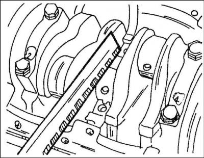
8. Using the measuring ruler included in the kit "Plastigage" measure the crushed strips of material at the widest point. If this value exceeds 0.17 mm for main bearings, the bearing caps must be replaced with new ones, and it must be taken into account whether the journals were previously ground.

9. To check the clearances of the remaining bearings, you need to check the crankshaft and take measurements on the other two connecting rod bearings. If there is no set "Plastigage", but you can use a dial bore gauge, you can measure the clearances of the main and connecting rod bearings in the manner described below.

10. Install the bearing caps with inserted liners according to the bearing numbers on the cylinder block and tighten the bolts with a tightening torque of 65 Nm. It is imperative to pay attention to the fact that the liners are in their original places. If the clearances of the connecting rod bearings are measured, it is necessary to insert the liners into the connecting rods and into the caps and screw the caps with the same nuts, tightening them with a torque of 30 Nm.


10. Install the bearing caps with inserted liners according to the bearing numbers on the cylinder…


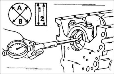
11. Measure the inner diameters of the bearings. In doing so, observe the direction of measurements A and B and the locations of measurements 1 and 2. In this way, you can determine the deviation from the circle (A and B) and the taper value (1 and 2). Record the results obtained for each bearing.

11. Measure the inner diameters of the bearings. In doing so, observe the direction of measurements…


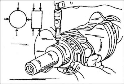
12. Measure the diameters of all bearing journals in order using a micrometer. Again, take measurements at specific locations, which are indicated by arrows. Record the measurement results for all bearing journals.

13. Subtract the measurements for the bearing diameters from the measurements for the inside diameters. The result is the bearing clearance (main or connecting rod) and must correspond to the value specified in the Specifications.

(The original source of the article can be found on the website «audimanual»)
The article was checked by auto expert Nikita Rudakov
This article is available at russian, bulgarian, belarusian, ukrainian, serbian, croatian, romanian, polish, slovak, hungarian

Share information:
Previous articles
Audi A3 Type 8L: Engine repair
Next articles

Checking, assembling and installing the connecting rod and…
Measuring cylinders
Removal and installation V-belt (diesel)
Removal and installation the cylinder head (diesel)


Similar articles on other Audi car models:
Checking the clearances between the bearings and the crankshaft… Audi 80 B2 (1979-1986)
Crankshaft — installation and checking of working clearance Audi 100 C3 (1982-1990, diesel)
Crankshaft — checking clearances in main bearings and… Audi A4 B5 (1994-2001)
Installing and checking the crankshaft Audi A6 C4 (1994-1997)
Checking the exhaust system Audi A8 D2 (1994-2002)
Checking the fuel level sensor «G» Audi Q5 Type 8R (2008-2017)
Checking the protrusion of the dowel pin from the crankshaft Audi A2 (1999-2005)
Link to this page in different formats


Visitor comments

No comments yet


How much will 49 + 17 =


A3(8L, 1996-2003) 
  • General information
  • User manual
  • Maintenance
  • Power unit
  • Engine repair
  • Lubrication system
  • Cooling system
  • Supply system
  • Fuel injection system
  • Exhaust system
  • Ignition system
  • Transmission
  • Manual transmission
  • Automatic transmission
  • Clutch and drive shafts
  • Chassis
  • Brake system
  • Front suspension
  • Rear suspension
  • Steering
  • Body
  • Ventilation and heating
  • Exterior (external elements)
  • Interior (internal elements)
  • Doors, covers and windows
  • Electrical equipment
  • Power devices
  • Lighting and appliances
  • Electrical circuits
 
AudiManual.ru © 2017-2026 · Mobile version · Feedback · Sitemap: EN BG BY UA RS HR RO PL SK HU · Site search · News and articles
80 B2 · 80 B3 petrol · 80 B3 · 80 B4 · 100 C3 diesel · 100 C3 petrol · 100 C3 · 100 C4 petrol · 100 C4 · A3 Type 8L · A4 B5 petrol · A4 B5 · A4 B6 petrol · A4 B6 · A4 B7 · A4 B8 · A6 C4 · A6 C5 · A6 C5 Allroad · A8 D2 · Q5 Type 8R · Q7 Typ 4L · Audi A2 ·
This site uses cookies 🍪. Click the button to accept this fact.