
Table of contents: Assembly of the connecting rod and… ↓ Installation of connecting rod and… ↓
1. All parts should be carefully checked. If parts show signs of grooves, gouges or wear, they should be replaced. The following checks should be made for pistons:
2. Measure the piston ring clearances in the grooves by height, installing the rings in turn in the corresponding grooves. The clearance between the ring surface and the piston groove surface is determined using a flat feeler gauge. If the ring clearance exceeds 0.12 mm, then the rings or pistons are worn. The nominal value is 0.02–0.07 mm.
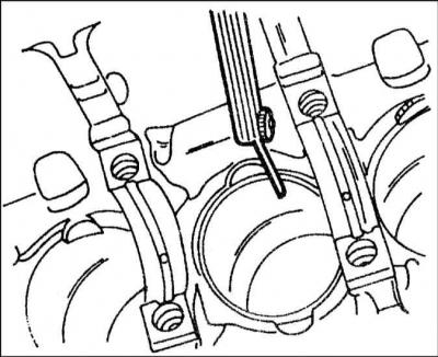
3. Insert all piston rings from the bottom of the cylinder block into the cylinders in order. Using an inverted piston, the rings should be pressed down approximately 15 mm. At the same time, both edges of the ring should be moved to measure the gap in the ring lock.
4. The nominal values are given in the Specifications. The wear limit also varies for different piston rings.
5. If the gap is too small (for example, if the ring is new), the edges of the ring should be filed down, for this purpose the file should be clamped in a vice. If the gap in the ring lock is too large, the corresponding ring should be replaced.
6. Piston pins and connecting rod bushings should be checked for wear and abrasion. If even one connecting rod is defective, the entire set should be replaced.
7. The connecting rod bearing nuts must be replaced.
8. The connecting rods should be checked for bending and twisting in a special device.
9. Check the connecting rod bolts for damage and replace if necessary. In this case, tension bolts are used and should be replaced with the same.
Assembly of the connecting rod and piston group
10. If the piston cooling oil nozzle was removed, it should be tightened together with the safety valve (27 Nm). The nozzles are located at the bottom of the cylinders.
11. If pistons are replaced, check that all pistons are the same type.
12. Heat the pistons to 60°C (put in hot water). Make sure you have a suitable tool that can be applied to the inside of the piston pin.
13. Press your fingers into the heated pistons and connecting rods by hand.
14. When assembling pistons and connecting rods, the following requirement must be met:
- Arrow on the piston bottom (or painted or stamped on the new piston) must face the front of the engine.
- The cast projections on the connecting rod and bearing cap must face the pulley.
- The cylinder number markings on the connecting rods and bearing caps must match.
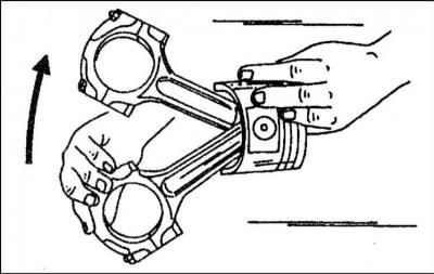
15. Check that after assembly the piston can swing freely on the connecting rod when moved in the direction of the arrow.
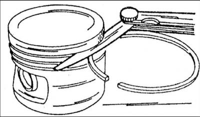
16. Using piston ring pliers, install the rings into the grooves one by one. Both compression rings can be mixed up, so it is necessary to check their cross-section before installing. In addition, both compression rings are marked on one side with the word "Top" or "Oben" and this designation should be read from above after installing the ring.
17. Install the three-piece oil scraper ring, spacing the locks evenly.
Installation of connecting rod and piston group
18. Lubricate the cylinders well.
19. Lay out all connecting rods according to cylinder numbers. The cast projections on the connecting rods and bearing caps should face the crankshaft pulley.
20. The arrows on the bottom of the pistons should point towards the front of the engine.
21. Place the piston ring locks at equal distances around the piston circumference, i.e. 120° apart.
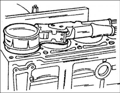
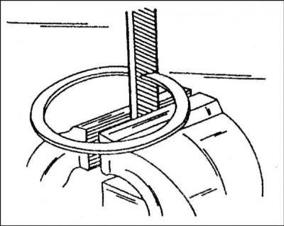
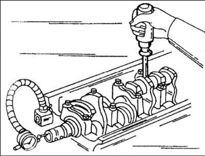
22. Position the piston ring tensioner as shown in the illustration and press the piston rings into the grooves. Make sure they are pressed in well.
23. Place short pieces of rubber or plastic tubing over the connecting rod studs to avoid scratching the cylinders.
24. Turn the crankshaft until the two journals are in the BDC position.
25. Push the connecting rod into the cylinder from above. The engine must be laid on its side to do this, so that the connecting rods can be brought to the bearing journals without scratching the cylinders or the connecting rod journals. The connecting rod bearing shell should already be in the connecting rod, with the protrusion in the recess.
26. Push the piston in until the rings are pushed into the cylinder one by one and the connecting rod base sits on the crankshaft journal. Be careful not to scratch the bearing journal.
27. Place the second bearing shell in the cover, lubricate the shell well, put the cover on the connecting rod studs and lightly hammer it in. The rubber tube sections must be removed beforehand. It is imperative to pay attention to the fact that the cast projections on the connecting rod and the connecting rod bearing cover match, otherwise you can make a mistake at the last moment.
28. Lubricate the mating surfaces of the nuts on the connecting rod bearing caps with oil.
29. Tighten the connecting rod bearing cap nuts alternately to a torque of 30 Nm and from this position tighten another 90°, i.e. a quarter of a turn.
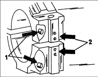
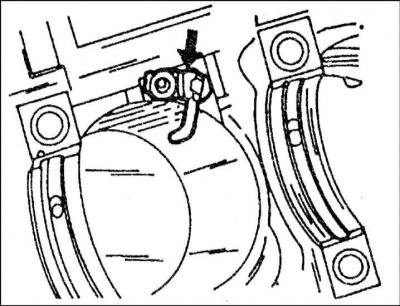
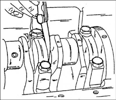
30. After tightening the connecting rod bearings, each bearing should be inspected again. Experience shows that defects in connecting rod bearings sometimes appear after repairs have been completed, when the bearing cap and connecting rod are not tightened perfectly. The number 1 in the illustration indicates both of the above-mentioned cast projections, and the number 2 indicates the connecting rod bearing cap and connecting rod, in this case for the second cylinder. These marks should be located opposite each other on all connecting rods. Such an inspection must be carried out before closing the engine crankcase.
31. After installing the connecting rods, the crankshaft should be turned several times to determine if there is any jamming. If there is, you need to check again whether the pistons are in the correct position, i.e. the arrows on the bottoms should be pointing forward (towards the pulley).
32. Using a feeler gauge, check the connecting rod side clearance to the crankshaft web. At the same time, press the connecting rod bearing to the right to measure the clearance with a feeler gauge. This is the connecting rod bearing axial clearance, and it should not exceed 0.37 mm. Install the oil pan.
The tightening torque of the mounting bolts is different for them.
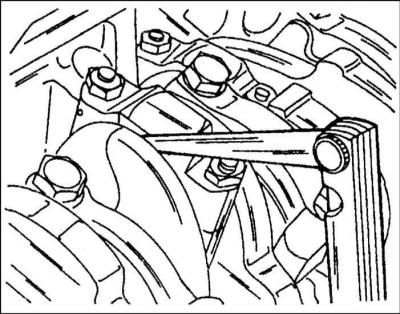
33. From the front of the engine, loosen the crankshaft pulley bolts (torsional vibration damper), holding the flywheel.
34. On cars with automatic transmission unscrew the drive disk in the manner described above.
35. Remove the cylinder head together with the intake manifold and exhaust manifold. Some parts are removed when the engine is removed (depending on its type).
36. Remove the pulley from the coolant pump and the lower timing belt cover.
37. Mark the direction of rotation of the timing belt with paint on the outside.
38. After loosening the belt tension nut, remove the toothed belt from the drive gears and tensioner. The camshaft(s) must not be turned after this.
39. Unscrew the oil pan.
40. Remove the oil pump.
41. If necessary, remove only the crankshaft, the pistons and connecting rods can be left in the cylinder block. Otherwise, remove the pistons and connecting rods. If the pistons and connecting rods remain in the block, mark the connecting rod bearing caps in order, remove them and store them together with the bearing shells. Do not forget that damaged tension bolts must be replaced.
42. Mount the dial gauge (indicator) on a stand to the front side of the cylinder block or secure it with a magnetic mount to the cylinder block, placing the feeler gauge against the crankshaft. Using a screwdriver, press the crankshaft in one direction, set the dial gauge to zero and press the shaft in the other direction. The dial gauge will show the axial clearance of the crankshaft and this value should be recorded. If it exceeds 0.25 mm, this should be taken into account during assembly. The center bearing shells are equipped with adjusting half rings that determine the axial clearance.
43. If a pointer gauge is not available, the clearance can be measured on the middle bearing between the bearing flange and the crankshaft surface using a blade-type feeler gauge. To check with a feeler gauge (thickness not more than 0.25 mm), the shaft must be pressed to one side.
44. Loosen the bolts securing the sealing flange on the front side of the engine and remove the flange with the gasket.
45. Remove the engine intermediate plate, unscrew the seal flange bolts and remove the flange with the seal. The intermediate plate is guided by guide bushings.
46. Loosen the crankshaft bearing cap bolts gradually in a crisscross pattern and remove them one by one. Make sure the cap numbers are clearly visible. Cap #1 is located on the pulley side.
47. Remove the bearing shells and main journals and store them with their respective bearing caps. Note that some shells have oil grooves and others do not.
48. Carefully remove the crankshaft from the engine crankcase.
49. Remove the remaining bearing shells from the crankcase and store them with the other bearing shells and caps. These shells are provided with lubrication channels and must be reinstalled in the crankcase during assembly.
50. Remove the lower half rings on the middle bearing. They should be marked on the side.