
Table of contents: Examination ↓ Assembly ↓
Examination
Cylinder head
1. Carefully inspect the head surfaces for cracks and damage. If any damage is found, contact a specialist.
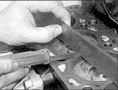
2. Using a ruler and feeler gauge, check the head surface for deformation; if necessary, the head must be machined. For this, contact a specialist.
Camshaft
1. Inspect the camshaft cams and bearing journals for wear and damage. If necessary, replace the camshaft, head and bearing caps.
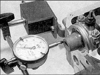
2. Measure the camshaft free play using a special measuring device.
3. Check the lubrication clearance of each camshaft bearing.
4. Clean the bearings and bearing caps with solvent. Install the shafts in place. Place a strip of measuring plastic on each bearing. Install the bearing caps and tighten the cap bolts.
5. Unscrew the bolts and remove the covers. Compare the width of the compressed strip with the measurement table. Replace the camshaft or cylinder head if necessary.
6. Clean off any remaining plastic.
Valves
1. Inspect the heads and valve seats. If the heads and seats are slightly burnt, you can polish them yourself with a special abrasive paste, but it is better if you contact specialists.
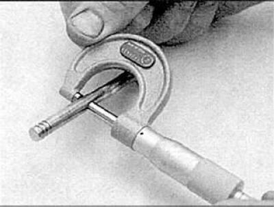
2. Measure the valve stem diameters.
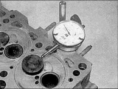
3. Check the clearance between the valve stem and the guide bushing; if it exceeds the permissible limits, contact a specialist.
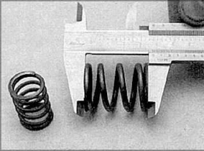
4. Inspect the valve springs for damage and compare their length with the length of the new springs. Replace the springs if necessary.
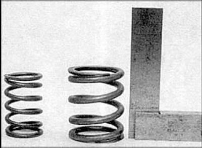
5. Check that the springs are straight.
Assembly
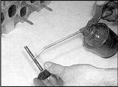
1. In order to achieve complete tightness between the valve and its seat, it is necessary to grind the contact surfaces of the valve and seat.
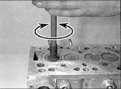
2. Apply a special abrasive paste to the valve head, insert it into place and turn it to the sides using a special tool.
3. Install the spring seats.
4. Lubricate the valve stems with oil and insert them into place.
5. Place plastic caps on the rods.
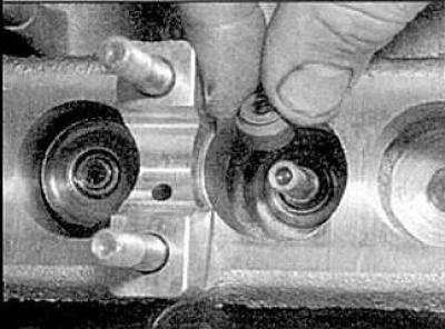
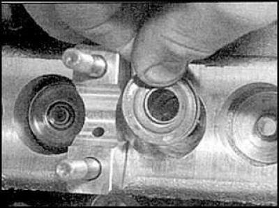
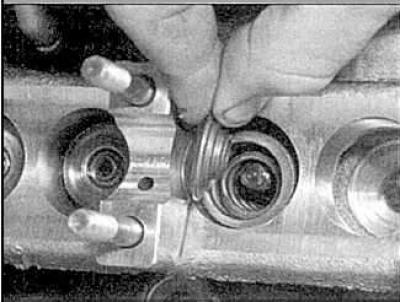
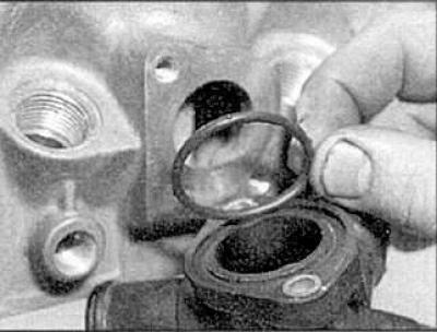
6. Install the piston rod seals and remove the protective caps.
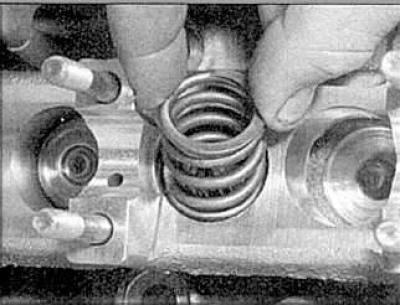
7. Install the springs.
8. Install the spring plates.
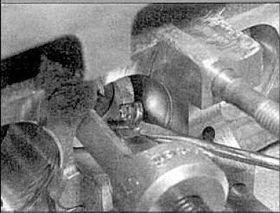
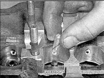
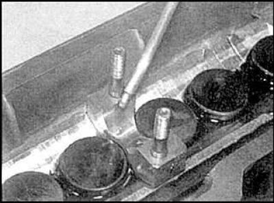
9. Compress the springs and insert the cone bushings.
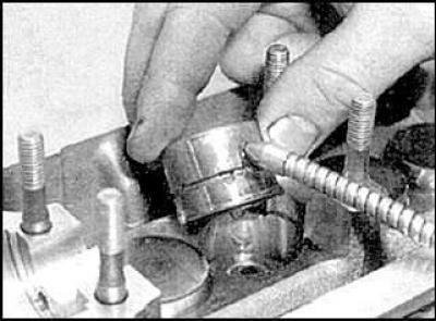
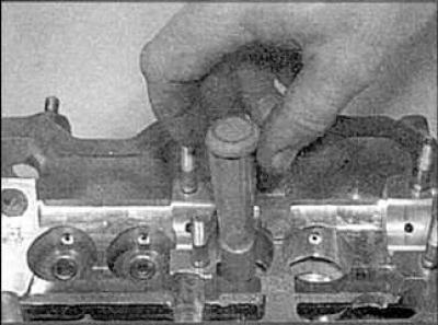
10. Lubricate and install the tappets.
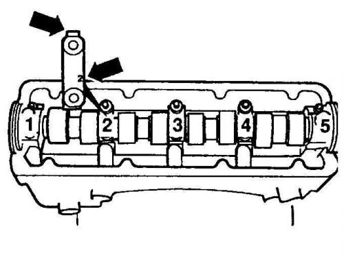
ADR engines
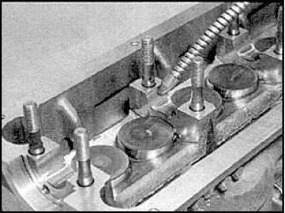
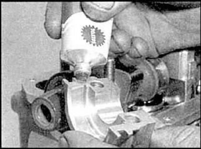
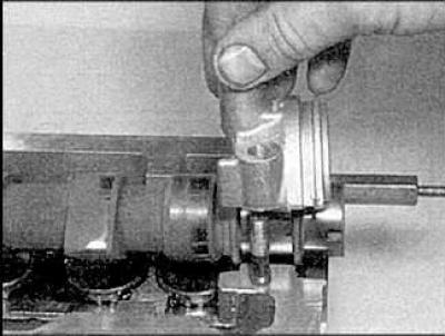
1. Lubricate the bearings and cams of the shafts and install the shafts. Install the shaft seals, install the automatic shaft adjuster. Lubricate and install the bearing caps.
2. Tighten cover bolts N₂ and 4.
3. Tighten the cover bolts N1.
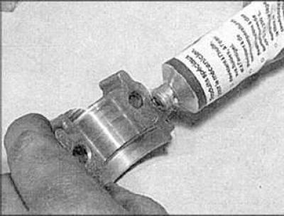
4. Remove the camshaft adjuster stopper and apply sealant to the mating surfaces of the combination cover. Install the cover and tighten the bolts.
5. Tighten cover bolts N3 and 5.
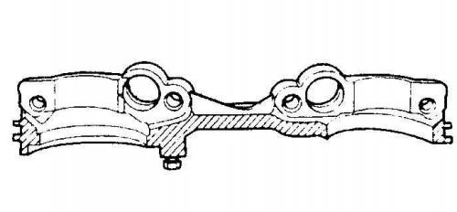
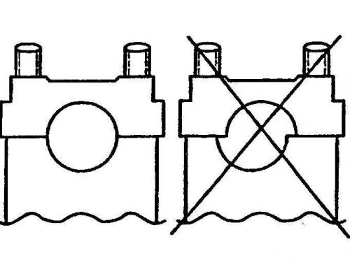
Correct placement of lids
Engines AAE, ABK, AAD, 1Z, AHU
1. Lubricate the bearings and shaft cams.
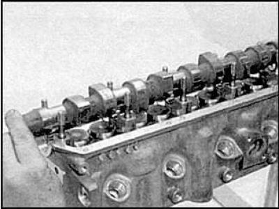
2. Install the shaft.
3. Lubricate and install the camshaft oil seal.
4. Install covers N₂ and 4 and tighten the bolts.
5. Apply sealant to the joints of cover N1, install covers N1, 3 and 5 and tighten the bolts.
ACE Engines
1. Lubricate the bearings and camshafts and install the shafts.
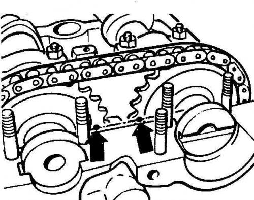
2. Install the chain on the camshaft sprockets. Align the timing marks.
3. Install the exhaust valve shaft seal.
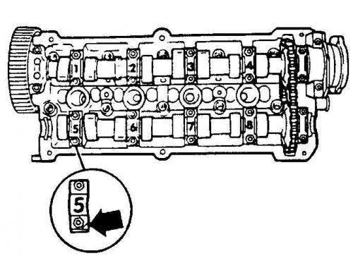
4. The bearing cap marks (arrow) must point towards the intake manifold.
5. Install caps N₂ and 4 and tighten the nuts, then install the remaining caps and tighten their nuts.
Engines AAR, AAN, AAS
1. Lubricate the bearings and camshafts and install the shafts.
2. Install the camshaft and camshaft seals.
3. Apply sealant to the joints of cover N4.
4. Install covers N₂ and 4 and tighten the bolts.
5. Apply sealant to the joints of cover N1.
6. Install covers N1 and 3 and tighten the bolts.
Engines ABP, AAT, AEL
1. Lubricate the bearings and camshafts and install the shafts.
2. Install the camshaft and its seals.
3. Apply sealant to the joints of cover N4.
4. Install caps N₂ and 4 and tighten the nuts.
5. Apply sealant to the joints of cover N1. Install covers N1 and 3 and tighten the bolts.
All types of engines
Install the remaining parts. Install the coolant hose.