
Table of contents: Removal ↓ Examination ↓
Crankshaft assembly (aAN, AAR engines)
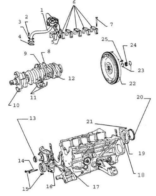
- 1. Oil receiver tube
- 2. Bolt, 10 Nm
- 3. Locking plate
- 4. Gasket
- 5. Bolt, 10 Nm
- 6. Main bearing caps
- 7. Bolt, 65 Nm
- 8. Thrust half rings of main bearing caps
- 9. Upper main bearing shells
- 10. Lower main bearing shells
- 11. Thrust half rings of the cylinder block
- 12. Crankshaft
- 13. Seal
- 14, 15. Bolt, 10 Nm
- 16. Oil pump
- 17, 18. Gasket
- 19. Rear oil seal holder
- 20. Seal
- 21. Bolt, 20 Nm
- 22. Flywheel
- 23. Retaining rings
- 24. Guide bearing
- 25. Bolt
Warning: When measuring axial clearance, do not turn the crankshaft.
Warning: Locking plate 3 must be replaced.
Warning: Gasket 4 must be replaced.
Warning: Main Bearing Caps 6: The first bearing cap is located on the crankshaft pulley side. Note the offset location of the bearing shell bedding and mounting bolt bosses.
Warning: When installing the main bearing cap thrust half rings 8, pay attention to the orientation of the rings.
Warning: Install the upper main bearing shells 9 together with the thrust half rings.
Warning: Lower main bearing shells 10 are not interchangeable.
Warning: Press out oil seal 13 using tool 320 3. Lightly lubricate the working and outer edges before installation. Install using mandrels from kit 2080 A. Press in until it stops using mandrel from kit 2080 A.
Warning: When installing oil pump 16, ensure correct fit on the crankshaft.
Warning: Gaskets 17 and 18 must be replaced.
Warning: Remove oil seal 20 using tool 2086. Do not lubricate during installation, as the oil seal from the repair kit is pre-lubricated. Install using the tool included in the repair kit. Remove the tool and press in with mandrel 2003/1 until it stops.
Warning: Before removing flywheel 22, apply orientation marks in relation to the crankshaft.
Warning: Tighten bolt 25 to 350 Nm and turn an additional 1/4 turn (90°).
Removal
1. Remove the pistons and connecting rods.
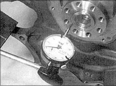
2. Check the free play of the shaft using a special measuring tool or using feeler gauges.
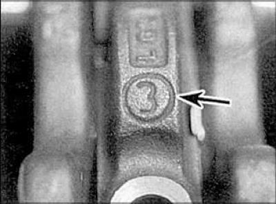
3. The main bearing caps must be numbered.
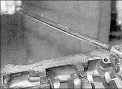
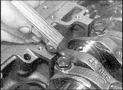
4. Loosen the main bearing cap bolts.
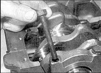
5. Remove the bolts.
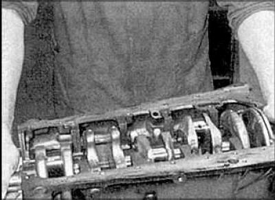
6. Remove the crankshaft.
7. Remove the liners from the cylinder block and remove the central bearing half rings.
Examination
1. Clean the crankshaft with solvent and dry it with compressed air.
2. Inspect the crankshaft bearings for wear, scratches, corrosion, or cracks. Rub a copper coin across the bearing. If the bearing rubs off the copper, the surface is too rough and needs to be resurfaced.
3. Inspect the crankshaft for cracks or other damage.
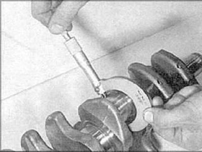
4. Measure the diameters of the main and connecting rod bearing journals.
5. Check the bearing journals for taper and out-of-roundness.
6. Check the crankshaft oil seal journals for signs of wear or damage. If the seals have worn through the grooves on the journals, the new seals will leak oil.
7. Measure shaft runout.
The original text is available on the website audimanual