
Table of contents: Checking the working clearance ↓ Crankshaft - final installation ↓
1. Installing the crankshaft is the first stage of engine assembly. At this stage, the crankshaft, cylinder block, crankcase and bearings should be cleaned, inspected and restored or replaced. Where removed, install the oil jets and tighten their mounting bolts with the tightening force specified Specifications.
2. Place the cylinder block on a clean, level work surface with the crankcase facing up. Wipe the inside surfaces of the main bearing caps and the corresponding recesses in the crankcase with a clean cloth - they must be spotlessly clean.
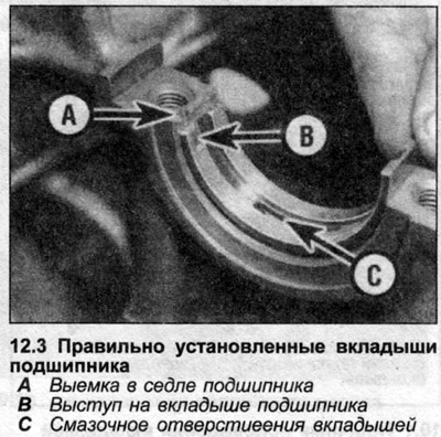
3. Clean the back surface of the new bearing shells with a cloth and place them in their working position in the crankcase. Make sure that the locating tabs on the shells fit into the corresponding recesses in the crankcase and that the oil holes are properly aligned (see illustration). Do not hammer or force the bearing shells into place. It is critical not to damage or contaminate the bearing surfaces.
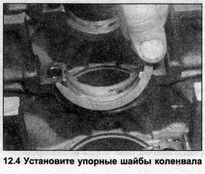
4. Install thrust washers on each side of bearing #4 (5-cylinder engines). Apply a small amount of grease to hold the washers in place. Make sure they are seated correctly in the grooves, with the grease tips facing outward (see illustration).
5. Wipe the installed main bearing shells and crankshaft journals again with a clean cloth. Make sure that the oil holes in the crankshaft are not clogged, as any grains left here will fall on the new shells when the engine is first started.
6. Carefully place the crankshaft into the crankcase, being careful not to displace the bearing shells.
Checking the working clearance
7. There must be a gap between the crankshaft and the bearing shells to allow the grease to circulate. This gap cannot be checked with a feeler gauge, so a special tool called Plastigage is required. The tool consists of a scale and plastic threads of round cross-section. Proceed as follows.
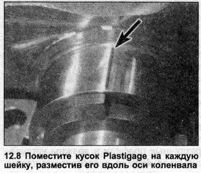
8. Cut several pieces of Plastigage slightly shorter than the crankshaft journal length. Place one piece on each journal, parallel to the crankshaft axis (see illustration).
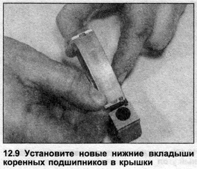
9. Wipe the back surfaces of the new lower main bearing shells and install them into the caps so that the mounting protrusions fit into the corresponding recesses (see illustration).
10. Wipe the bearing surfaces clean and, if possible, lightly coat them with silicone repellent to prevent the Plastigage from sticking. Install the caps, each one exactly in its original position, using the manufacturer's marks for orientation. The caps should be installed so that the recesses for the bearing locating protrusions are on the same side as in the bearing seat.
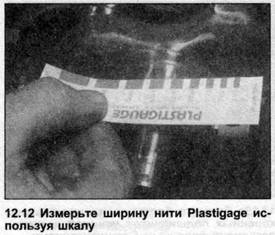
11. Working from the center bearing cap outward, tighten the bolts by turning them half a turn at a time to the first stage tightening torque (see Specifications). Do not move the crankshaft while the Plastigage is under the bearings. Gradually unscrew the bearing cap bolts and remove them, being careful not to displace the Plastigage.
12. Measure the width of the Plastigage thread using the tool scale (see illustration). This measurement is equal to the bearing operating clearance - compare it with the data given in the Specifications. If the clearance is outside the permissible deviations, the cause may be foreign particles trapped under the liners; try cleaning them and rechecking. If the results are still unsatisfactory, remeasure the neck diameters and check the insert sizes. If one end of the Plastigage is thicker than the other, the necks may be tapered and need to be resharpened.
13. If the clearance is within specification, carefully scrape away any remaining Plastigage from the journals and bearings. Use a soft plastic or wooden scraper to avoid scratching the surfaces.
Crankshaft - final installation
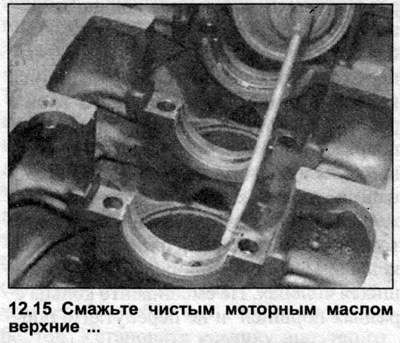
14. Lift the crankshaft out of the crankcase. Wipe the bearing seating surfaces in the crankcase and covers.
15. Generously lubricate the bearing shells in the crankcase with clean, specified grade motor oil (see illustration).
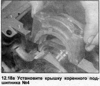
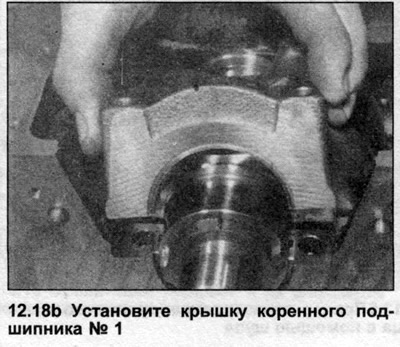
16. Lower the crankshaft to the working position so that the connecting rod journal of cylinder No.1 is at BDC.
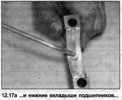
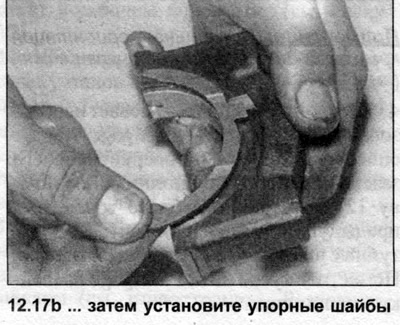
17. Lubricate the lower shells in the main bearing caps with clean engine oil, then install thrust washers on both sides of the bearing cap No.3 or No.4 (depending on the model), remembering that the protrusions of the washers must fit into the recesses in the bearing cap (see illustrations). Make sure the locating tabs on the inserts are still seated in the corresponding grooves in the covers.
18. Install the main bearing caps, observing their order and orientation - bearing cap No.1 should be located at the front end of the engine, and the grooves for the mounting protrusions of the liners in the bearing seats and caps should be facing the same way (see illustrations). Insert the bearing cap mounting bolts and tighten them by hand only for now.
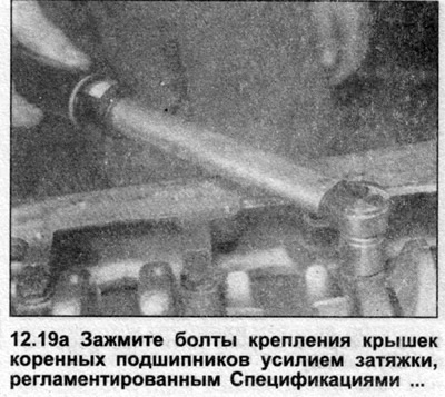
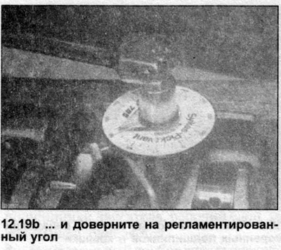
19. Moving from the central bearing cover to the outer covers, tighten the bolts of their fastening with the tightening force specified Specifications. Where tightening is divided into several stages, tighten all bolts to the force of the first stage, then repeat the action in the same sequence for the next stage, etc. (see illustrations).
20. Check that the crankshaft rotates freely by turning it by hand. If resistance is felt, check the running clearances as described above.
21. Perform a crankshaft end clearance check as described at the beginning Chapters 8.
22. Install the pistons and connecting rods or connect them to the crankshaft (see Chapter 14).
23. See. Section 1A and do the following:
- a) Install the crankshaft rear oil seal housing together with the new oil seal (Section 1A).
- b) Install the oil pump and suction pipe, the sump partition and the sump itself (Section 1A).
- c) Install the flywheel and clutch or drive disc (depending on the clothes) (Section 1A).
- d) Install the crankshaft sprocket and timing belt (Section 1A).