
Table of contents: Cleaning ↓ Inspection ↓
Cleaning
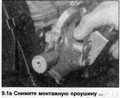
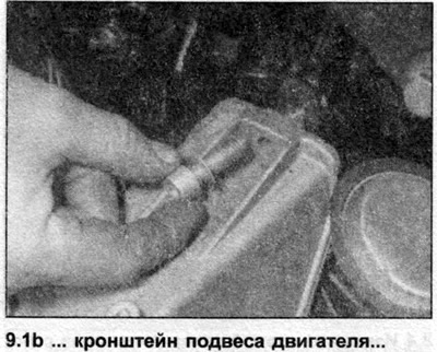
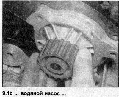
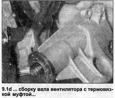
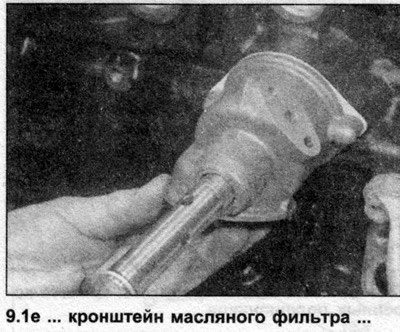
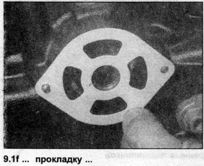
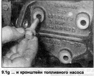
1. Remove all external components from the block including mounting eyes, engine mounts, water pump, fan shaft/coupling assembly, oil filter bracket, fuel injection pump bracket and electrical switches/sensors (see illustrations). For complete cleaning, the cork plugs should also be removed. Drill a small hole in each plug, then screw self-tapping screws into the holes. Remove the plugs by pulling the screws with pliers.
2. Clean all traces of gasket and sealant from the cylinder block/crankcase, taking care not to damage the contact surfaces.
3. Remove all oil channel plugs (where are there). The plugs are usually a very tight fit - you will probably have to drill them out and then re-tap the crankcase holes. In any case, use new plugs when reassembling.
4. If the crankcase is very dirty, have it steam cleaned by an auto repair shop. After steam cleaning, all oil holes and passages in the crankcase should be flushed. Run warm water through the internal passages until the water runs clear. Dry the passages thoroughly with compressed air and apply a thin layer of oil to all contact surfaces of the block and cylinder walls to prevent corrosion.
Warning: When using compressed air, protect your eyes with goggles.
5. If the crankcase is not very dirty, clean it with hot soapy water and a stiff brush. Regardless of the cleaning method used, be sure to thoroughly clean all oil holes and passages, and then dry all components well. Protect the cylinder walls from corrosion as described above.
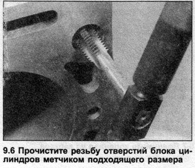
6. All tapped holes must be clean to ensure accurate tightening torques during assembly. Run a suitable size tap through each hole to clean and restore any rust, deposits or sealant on the threads (see illustration). When finished, blow the holes again with compressed air to clear them of any particles that have appeared as a result of this action.
Note: Make sure all threaded holes are free of moisture as the crankcase may crack under the hydraulic pressure generated when a bolt is screwed into a hole containing liquid.
7. Apply a suitable sealant to the new oil passage plugs and insert them into the holes in the block. Tighten them securely.
8. If the engine is not going to be reassembled right away, cover it with a large plastic bag to keep it clean; lubricate all contact surfaces and cylinder walls with oil to prevent corrosion.
Inspection
9. Inspect the crankcase parts for cracks and corrosion. Check the integrity of the threads in the holes. If there are signs of internal coolant leakage, have a specialist diagnose the block using special equipment. If defects are found, repair (if possible) or replace the assembly.
10. Check the walls of each cylinder for nicks and notches. If such damage is found, inspect the corresponding piston (see Chapter 7 of this Section). If the damage is not deep, it may be possible to restore the block by boring out the cylinders. Consult a specialist for advice.
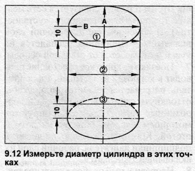
11. To make an accurate assessment of cylinder wall wear, measure their diameter at several points as follows. Insert a bore gauge into cylinder #1 and take three measurements parallel to the crankshaft axis - 10 mm from the top edge of the cylinder, in the middle of the cylinder and 10 mm from its bottom edge.
Note: Mount the engine block on a workbench to perform this procedure. Taking measurements on an engine mounted on a stand may result in inaccurate results.
12. Rotate the bore gauge 90° (perpendicular to the crankshaft axis) and repeat the measurements (see illustration). Record the results of all six measurements and compare them with the data given in the Specifications. If the difference in the diameters of any two cylinders exceeds the wear limit, or if the diameter of even one cylinder exceeds the maximum allowable value, all four cylinders must be bored and oversized pistons installed.
13. Using the piston diameter data recorded earlier (see Chapter 7), calculate the clearance between the piston and the cylinder wall. Manufacturers do not provide any values for this clearance, so consult your Audi dealer for advice.
14. Place the cylinder block on a workbench with the crankcase facing down. Using the edge of a ruler and a set of feeler gauges, measure the deformation of both contact surfaces of the cylinder head. Manufacturers do not provide a maximum permissible value, but it is approximately 0.05 mm. If the deformation exceeds this figure, it may be possible to regrind the block - consult with the dealer.
15. Before the engine can be reassembled, the cylinder walls must be honed, i.e., finely shaded with an abrasive tool. This is done so that the new piston rings will rub against the cylinder walls. There are two types of honing tools, both of which are driven by an electrically powered rotary tool, such as a drill. There are two types of hones - a flexible one, such as a bottle brush, and a hone with spring-loaded heads. A less experienced mechanic will probably find it easier to work with a flexible hone. In addition, you will need kerosene or special oil, rags, an electric drill, and safety glasses.
Note: If you do not want to hone your cylinders yourself, leave this work to an auto repair shop.
16. Perform honing as follows.
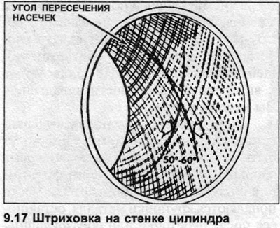
17. Mount the hone on the drill. Lubricate the cylinders generously with honing oil, compress the hone heads and push them into the first cylinder. Turn on the drill and move the hone up and down in the cylinder at a speed that will make a fine crosshatch on the walls. Ideally, the crosshatch lines should intersect at an angle of approximately 60° (see illustration). Some piston ring manufacturers may specify a crosshatch angle less than the traditional 60° - read the instructions supplied with the rings and follow them carefully.
Note: When working with hone, protect your eyes with goggles.
18. Make sure to use enough lubrication and do not remove more metal than absolutely necessary. Do not remove the hone from the cylinder while it is rotating. Turn off the drill and continue to move the hone up and down until it stops, then squeeze the heads and remove the hone. If using a flexible hone, stop the drill, then remove the hone from the cylinder by turning it in the direction of rotation.
19. Wipe off the oil and fine metal shavings with a rag and move on to the next cylinder. When all four cylinders are honed, thoroughly wash the cylinder block in hot, soapy water. A cylinder can be considered clean when, after running a thick white cloth (lint-free) moistened with clean engine oil over its wall, the cloth remains clean. Make sure to brush all the grease holes and channels and flush them with water.
20. Rinse the block with clean water, dry it, and coat all treated surfaces and cylinder walls with engine oil to prevent corrosion.
21. Install all components removed in step 1.