
Note: You can purchase either a new or remanufactured cylinder head. Keep in mind that special tools are required for disassembly and inspection, and new parts may not always be available immediately. Therefore, it may be more practical to purchase a ready-made remanufactured head than to disassemble, inspect, and remanufacture the old one.
Disassembly
1. Remove the cylinder head from the block as described in section A or B this chapter. Remove the camshaft sprocket as described in Part A or B of this chapter.
2. On diesel models, remove the injectors and glow plugs (see chapters 4B or 5B).
3. If necessary, remove the cooling system outlet flange together with the gasket/O-ring.
4. On AHL engines, unscrew the temperature sensor from the cylinder head.
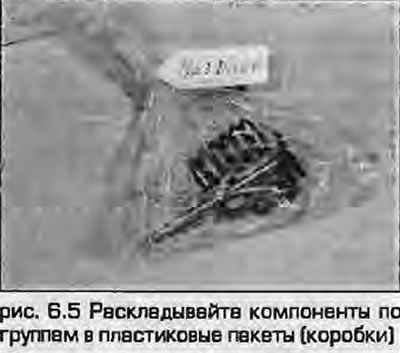
5. It is very important to group components together when removing them to facilitate installation. If they are not installed in the correct places, increased wear may occur. Place groups of components in plastic bags - mark the containers, for example: No.1 exhaust, No.2 intake, etc. (Fig. 6.5). Cylinder No.1 is on the timing belt side.
6. There are manufacturer's marks on the camshaft support caps; if for some reason they are not visible, use a scriber to apply your own when removing them.
7. The camshaft support covers are removed as follows.
Engines ADR, AFY, AEB, AJL
8. At the front of the camshaft, remove the Hall sensor, unscrew the bolt from the camshaft, remove the conical washer and the Hall sensor plate.
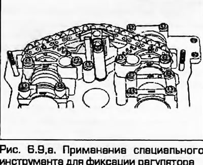
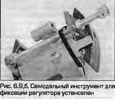
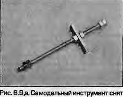
9. The automatic camshaft phase adjuster must be locked before removal. Audi mechanics use special tool 3366 for this purpose (fig. 6.9, a). A similar homemade tool can be made from a threaded rod, a nut, and a small metal plate to compress the regulator. For safety, tie the homemade tool with a plastic tie (fig. 6.9, b, c).
 |
 |
10. Align the chain and sprockets with the arrows on the rear camshaft bearing caps, and mark the chain and sprockets. Note that the distance between the two marks should be equal to 16 chain rollers. The mark on the exhaust camshaft is slightly offset toward the center of the cylinder head.
11. Loosen cover bolts 3 and 5, then 6 on both camshafts (Fig. 6.11).
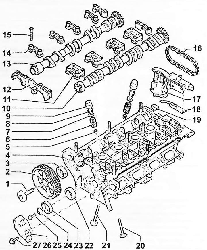
Fig. 6.11. Cylinder head components (engines ADR, AFY, AEB, AJL): 1. Camshaft sprocket mounting bolt; 2. Camshaft sprocket; 3. Seal; 4. Cylinder head; 5. Oil seal; 6. Valve spring; 7. Upper valve spring seat; 8. Rusks; 9. Hydraulic pusher; 10. Intake camshaft; 11. Intake manifold support cover; 12. Front combination support cover; 13. Exhaust camshaft; 14. Bearing cover, exhaust camshaft; 15. Camshaft support cover mounting bolt; 16. Drive chain; 17. Automatic camshaft phase regulator; 18. Rubber seal; 19. Semi-circular rubber seal; 20. Exhaust valve; 21. Inlet valve; 22. Seal; 23. Hall sensor ring; 24. Cone washer; 25. Ring mounting bolt; 26. Hall sensor; 27. Hall sensor mounting bolt
Note: The covers are numbered from the rear side of the cylinder head, cover No.6 is a combined cover, installed on both camshafts.
12. Loosen the camshaft phase adjuster mounting bolts.
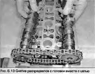
13. Gradually loosen the bolts securing covers 4 and 2 on both camshafts, remove both camshafts from the cylinder head together with the automatic chain tensioner (Fig. 6.13).
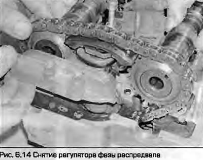
14. Unhook the regulator from the chain and remove the chain from the camshaft sprockets. Remove the seals from the camshafts (Fig. 6.14).
Engines ADP, AHL, 1Z, AFF, AFN, ANN, AHU
15. Loosen the nuts of support caps 5, 1 and 3, then caps 2 and 4 (Fig. 6.15). Loosen the nuts in a diagonal sequence, half a turn at a time, until they can be removed by hand. Keep the caps in the order in which they were installed.
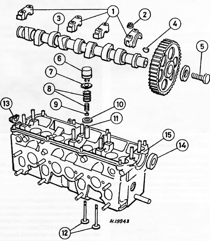
Fig. 6.15. Cylinder head components (engines 1Z, AHU, ANN. AFN and AFF): 1. Camshaft support cover; 2. Nut; 3. Camshaft; 4. Key; 5. Camshaft sprocket mounting bolt; 6. Hydraulic pusher; 7. Upper valve spring seat; 8. Valve spring; 9. Valve stem seals; 10. Lower valve spring seat; 11. Guide bushing; 12. Valves; 13. Semicircular seal; 14. Camshaft oil seal; 15. Cylinder head casting
Note: Covers are numbered 1 through 5 starting from the timing belt.
16. Remove the oil seal from the camshaft and discard it; a new one is required for installation (Fig. 6.16).
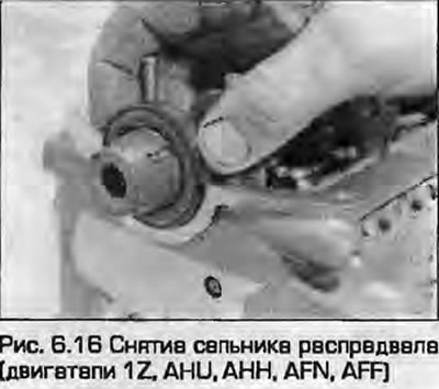
17. Carefully remove the camshaft from the cylinder head, holding it horizontally by the ends so as not to damage the supports.
All engines
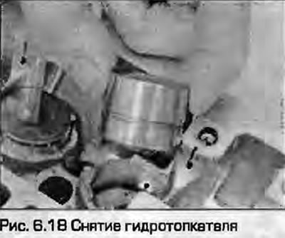
18. Remove the hydraulic tappets and place them upside down to prevent oil from leaking out (Fig. 6.18). It is recommended to store the tappets immersed in oil for the entire duration of the head repair. Remember the installation of each tappet so that you can install them in their proper places during assembly to avoid increased wear.
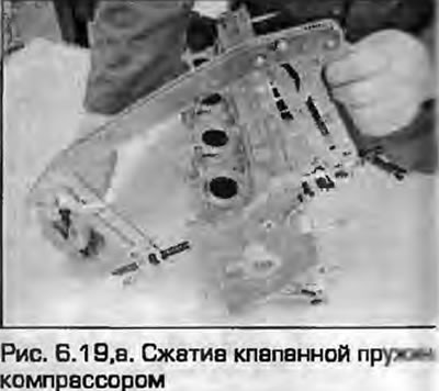
19. Turn the head upside down and lay it on its side. Using the valve spring compressor ("raskharivatel"), squeeze them one at a time to remove the breadcrumbs. If the top plate is "burnt", hit the top heel of the compressor with a hammer (covered with a cloth so that the crackers wouldn't suddenly fly apart), to free her (fig. 6.19, a, b).
 |
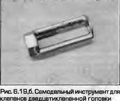 |
Note: On 20-valve engines, the access hole to the inlet valves is significantly smaller than the outlet valves - the standard compressor may be too large. If you don't have access to an Audi/VAG tool, you can make your own from a suitable nut, washer and metal rods welded together (fig. 6.19, a, b).
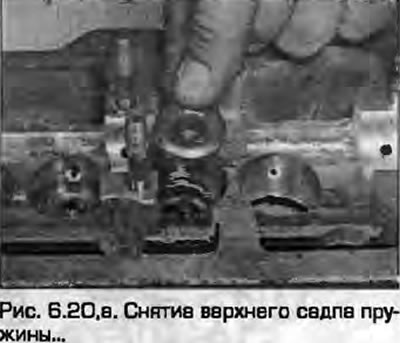
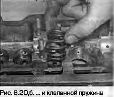
20. Release the compressor and remove the spring seat, valve spring (gasoline engines) or double valve spring (diesel engines) (fig. 6.20, a, b).
 |
 |
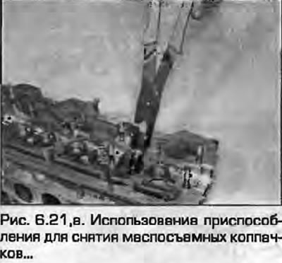
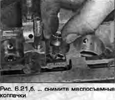
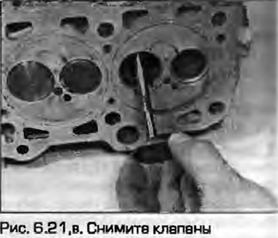
21. With pliers or a special puller (collet is convenient) pull the caps off the guide bushings, then (on diesel engines) remove the lower spring seat. Remove the valve itself from the valve seat side. Repeat the procedure with the remaining valves (fig. 6.21, a-c).
 |
 |
Cleaning
22. Scrape off all traces of the old gasket from the cylinder head. Scrape off all carbon deposits from the combustion chambers and passages, being careful not to scratch them. Do not use sandpaper coarser than 100, then wash the head thoroughly with kerosene or other suitable solvent.
23. Scrape off all carbon deposits from the valves. To make the job easier, you can use a round wire brush with an electric or pneumatic drive.
24. If the head is very dirty, it should be washed with steam. After washing, dry the head thoroughly and make sure all oil and water channels are clean. Throw away the seals - new ones are required for assembly.
Examination
Cylinder head
Note: On diesel engines, the valves and cylinder head are not subject to repair (the valves can only be ground, defective components are replaced with new ones.
25. Carefully inspect the head for cracks, visible signs of coolant leaks, and other damage. Pay particular attention to the areas around the valve seats and spark plug holes. If cracks are found between the valve seats, Audi experts say the head can be used if the cracks are no more than 0.6 mm wide. If more serious damage is found, the head must be replaced.
26. Minor burns on the seats can be removed by grinding the valves as described below. Serious burns on the seats require milling, however, this work should be entrusted to specialists.
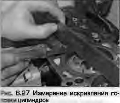
27. Using a steel ruler and a set of flat feeler gauges, inspect the head for curvature of the connector surface with the block in several places (Fig. 6.27). Compare the obtained measurements with the data given in Specifications. On petrol engines, if necessary, the head can be ground without going beyond the limits height specified in Specifications.
28. The minimum permissible head heights are given in Specifications.
Camshaft
29. Inspect the cams and bearing journals of the camshaft for obvious wear. Their surfaces should look smooth and semi-shiny. Inspect surfaces that look excessively shiny - they may be worn. There should be no scratches, scuffs, etc. If the hardened surface of the camshaft is worn, further wear will occur in an avalanche-like manner. A worn camshaft must be replaced.
Note: If the cam lobe tops are worn, inspect the corresponding tappets - they may also be worn.
30. If provided, inspect the distributor drive gear. Excessive play in the drive indicates a worn gear and leads to incorrect ignition timing.
31. If there are tarnished colors on the friction surfaces of the camshaft, it is possible that overheating occurred in these areas, most likely due to a lack of sufficient lubrication. Overheating can lead to shaft distortion - place the shaft on prisms and check its runout in the central journal. If the runout exceeds the permissible Specifications, the shaft must be replaced.
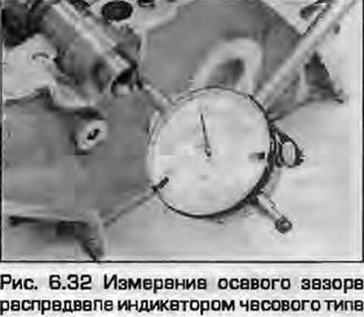
32. To measure the axial clearance of the camshaft, install the camshaft in the cylinder head, install the first and last bearing caps, tighten their fastening nuts to the specified torque for the first stage. Rest the leg of the dial indicator against the end of the shaft on the timing belt side, securing the device to the head. Move the camshaft to the stop at one end and zero the scale. Now move the camshaft to the stop at the other end of the head and read the indicator readings. Move the shaft again to the stop and make sure that the dial is set to zero (Fig. 6.32).
Note: When taking measurements, there should be no tappets in the head.
33. Compare the obtained data with the Specifications. If the gap is increased, either the camshaft or the cylinder head may be to blame. Worn parts must be replaced.
34. Now it is necessary to measure the clearance in the camshaft supports. The first method is difficult to access (due to the high cost of the tool), is as follows. Without installing the camshaft, install the covers of all the supports, then measure all the internal diameters of the plain bearings of the supports with a bore gauge. The next step is to measure all the diameters of the shaft journals with a verified micrometer. Subtracting the second results from the first will give the value of the gap in each journal.
35. The second method, more accurate, is to use a plastic measuring rod "Plastigauge". This method may be even more difficult to access - "Plastigauge" it is very difficult to acquire. But, the method is as follows.
36. Make sure that the shaft and bearing surfaces in the head are completely clean. Place the camshaft on a dry head.
37. Lay the section "Plastigauge" on the top of each neck, placing it parallel to the shaft axis.
38. Install the camshaft bearing caps into the head and tighten them sequentially to the specified torque in a diagonal sequence.
Note: If the cap fasteners need to be tightened in several stages, tighten them only to the torque specified for the first stage. Do not rotate the camshaft while taking measurements. Otherwise, you will get incorrect results.
39. Unscrew the nuts securing the supports and carefully remove the covers vertically upwards so as not to disturb them "Plastigauge". The flattened pieces of plastic should remain on the necks.
40. Attach the palette that comes with the "Plastigauge" to the sections and measure their width - calculate the gap on the scale.
41. Compare the obtained measurements with the data given in Specifications. If the gap exceeds the permissible limit, the camshaft and cylinder head must be replaced.
42. On DOHC engines, clearances are measured on both camshafts.
43. Finally, remove the bearing caps and camshaft, remove any stuck plastic residue.
Valves and related components
Note: On all engines, it is not allowed to grind the valve plates, they can only be lapped.
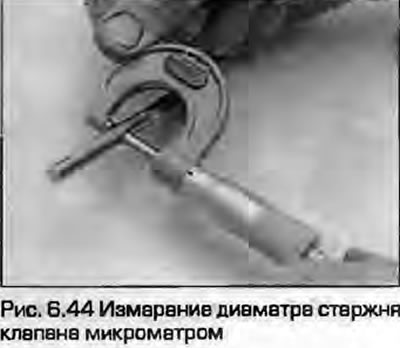
44. Visually inspect the valves for wear. There should be no changes in the stem diameters, burrs or deep scratches on them. Use a micrometer to measure the diameter of the valve stem in several places along its entire length (Fig. 6.44).
45. Valve plates should be free of cracks, burnouts and deep cavities. Minor pitting of the working chamfers can be removed by lapping during assembly, as described below.
46. The valve stem heel should not have excessive wear or metal chipping; these defects are possible due to faulty hydraulic lifters.
47. Insert the valve into its guide bushing and attach a dial indicator next to the disc. Slide the valve out of the bushing until its heel is flush with the end of the bushing. Measure the valve's swing in the bushing (Fig. 6.47).
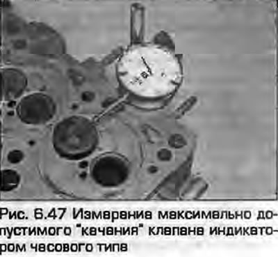
48. If the measured result exceeds the data prescribed Specifications, the guide bushing and valve are replaced together.
Note: The runner bushings are pressed into the head and require a hydraulic press to remove them. This work is best left to a suitably equipped workshop.
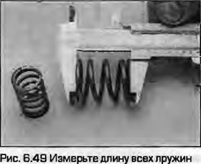
49. Measure the length of each spring with a caliper. Since the length of the springs Specifications is not prescribed, the only way left is to compare the length of the old spring with the length of the new one. Please note that valve springs are usually replaced during major repairs (Fig. 6.49).
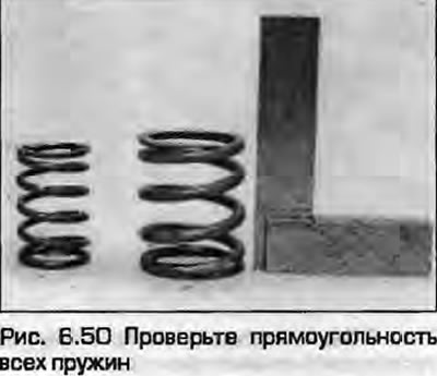
50. Check the spring for squareness by placing it on a plane next to the corner (Fig. 6.50). Replace crooked springs.
Assembly
51. To achieve tightness in the valve/seat pair, it is necessary to grind the valves. This requires coarse and fine grinding pastes and a device for grinding the valves - this can be either a collet tool or a suction cup tool. The drive can be either manual or mechanical.
52. Apply a small amount of thin paste to the working chamfer of the valve plate. Install the valve in its sleeve. Attach the tool and grind the valve to its seat with a back-and-forth rotation. Periodically lift the valve and move it in the seat so that the paste is distributed evenly (Fig. 6.52).
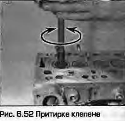
53. Continue grinding until a uniform matte strip appears not only on the valve, but also on the seat. Repeat the operation with the remaining valves.
54. If the valves and seats are so burnt that they require coarse paste for grinding, do not forget about the permissible height of the valve stem heel protrusion above the guide bushing - do not grind the valve seat into dust. The required heights are given in Specifications at the beginning of the chapter. If the permissible dimensions are exceeded, the hydraulic tappets will not be able to work satisfactorily.
55. Taking into account the above information, first grind the valves with a coarse paste. Wash off traces of the coarse paste and then grind with a fine paste until a uniform, slightly matte working surface of the chamfer is achieved.
56. Once all the valves have been lapped, remove all traces of lapping paste from the cylinder head and valves with solvent and dry thoroughly.
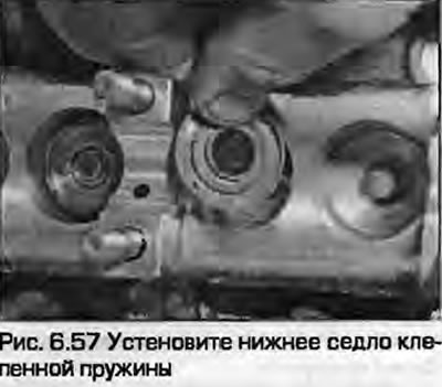
57. On diesel heads, first install the lower spring seat with the curved surface towards the head (Fig. 6.57).
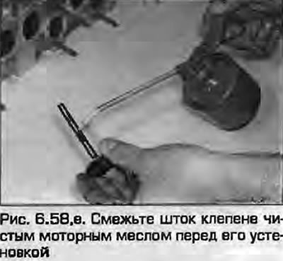
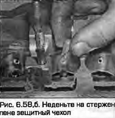
58. Working with each valve in turn, lubricate the valve stems with clean engine oil and insert them into the guide bushings. Place one of the protective plastic covers included in the valve stem seal kit over the valve stem to protect the seal during installation (fig. 6.58, a, b).
 |
 |
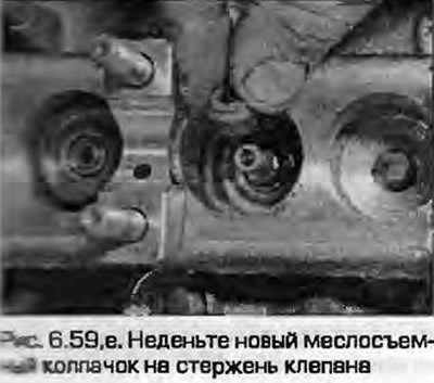
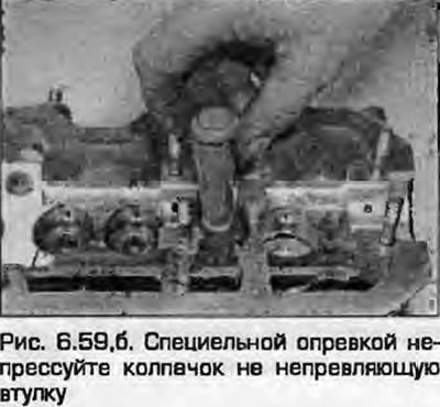
59. Dip the new valve stem seal into clean engine oil, place it on the valve stem and push it through the guide bushing. Using a head or a special mandrel, press the seal onto the bushing (Fig. 6.59). Remove the protective cover.
 |
 |
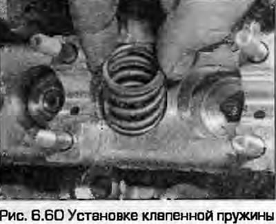
60. Place the valve spring(s) onto the valve stem (Fig. 6.60). On diesel engines, ensure that the springs are correctly seated in the lower seat.
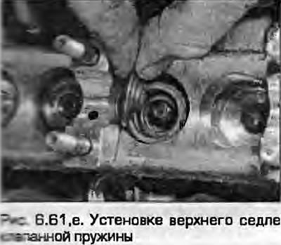
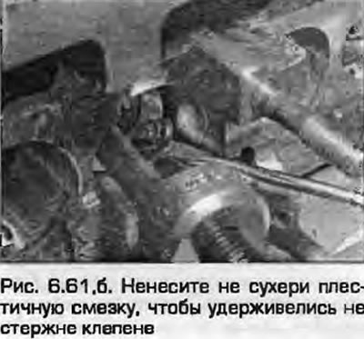
61. Install the upper seats on the spring. Using a spring compressor, compress them to install the crackers, fix them in the grooves on the valve stems. To facilitate fixing the crackers, lubricate them with a drop of plastic grease (Fig. 6.61). Smoothly release the compressor, make sure that the crackers are installed correctly. If the crackers are installed correctly, they should close.
 |
 |
62. Repeat the process with the remaining valves. To securely fix the crackers after installing them, lightly tap the valve stem legs with a hammer through a soft metal spacer so as not to damage the valves. Before installing the tappets, make sure the crackers are securely fixed once again.
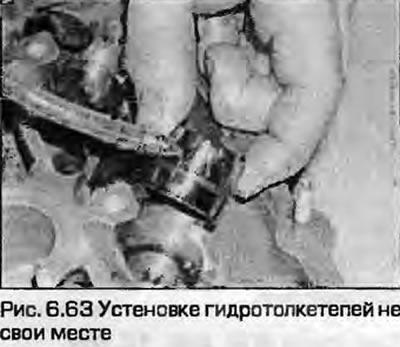
63. Lubricate the outside of the tappets with clean engine oil and install them in place. Push them in, twist them slightly until they stop against the valves, then lubricate the surfaces that contact the cams (Fig. 6.63).
Engines ADR, AFY, AEB, AJL
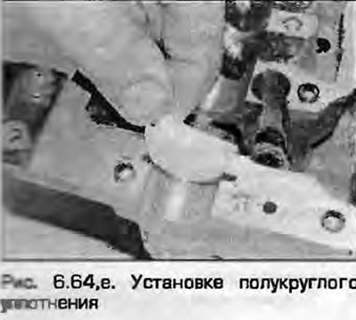
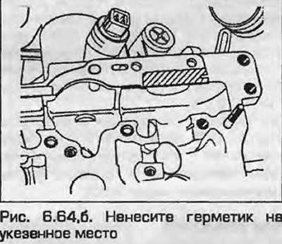
54. Place the rubber/metal gasket on the automatic phase controller together with the semi-circular seal (fig. 6.64, a, b) at the front of the cylinder head. If the gasket does not have sealant applied, apply a small amount of suitable sealant to the indicated area (Fig. 6.64).
 |
 |
55. Lubricate the camshafts and bearings with clean engine oil.
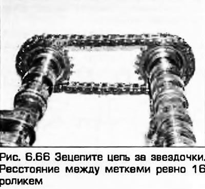
66. Hook the chain onto the camshaft sprockets so that there are 16 rollers between the sprocket marks (Fig. 6.66). Install the adjuster between the target arms and carefully lower the camshafts into place in the cylinder head, supporting the camshafts by the ends so as not to damage the journals and cams. Alternatively, you can place the camshafts together with the chain in the cylinder head, then slightly lift the camshafts by the sprockets to install the adjuster.
67. The camshaft seals can be installed at this stage or later. Dip the new seals in clean engine oil and place them on the front ends of the shafts. The seals are installed with the closed surfaces facing outward. Be careful not to damage the working edges of the seals. Install the seals in their seats.
68. Install the regulator bolts and tighten them to the specified torque.
69. Lubricate the upper surfaces of the bearing journals and install covers No.2 and No.4 on both camshafts. Make sure that the covers are installed correctly and tighten their mounting bolts to the specified torque.
Application: Covers are numbered from the rear of the engine guard.
70. Install covers No.1 on both camshafts and gradually tighten the mounting bolts to the specified torque.
71. Remove the locking tool from the automatic regulator.
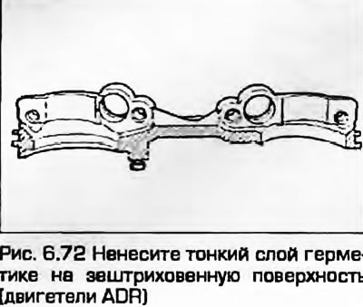
72. Apply a thin layer of sealant to the mating surface of the front combination cover and install it so that the seals are not distorted (Fig. 6.72). Gradually tighten the cover mounting bolts to the specified torque.
73. Install covers No.5 and gradually tighten the mounting bolts to the specified torque.
74. Install the Hall sensor plate to the front end of the intake camshaft and tighten the bolt to the specified torque.
75. Install the Hall sensor and tighten the mounting bolt.
ADP engines. AHL, 1Z, AFF, AFN, ANN, AHU
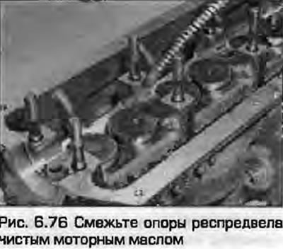
76. Lubricate the camshaft and bearing surfaces in the cylinder head with clean engine oil (Fig. 6.76).
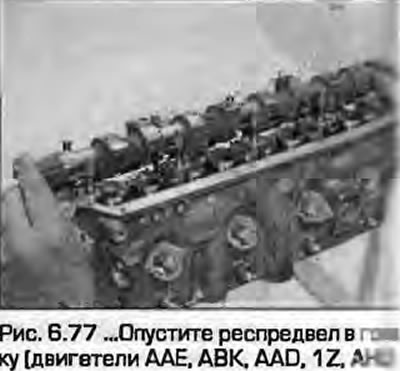
77. Carefully lower the camshaft into the cylinder head with the cams of the first cylinder facing up. When installing, hold the camshaft by the ends parallel to the head to avoid damaging the bearing surfaces (Fig. 6.77).
78. Dip the new seal into clean engine oil and install it on the front end of the camshaft with the closed surface facing outward. Be careful not to damage the working edges of the seal. Install the seal into its seat.
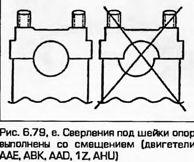
79. The bearing caps are numbered and have a mating lug on one side. If the caps are installed correctly, the numbers on the caps should be legible from the exhaust side of the cylinder head and the lugs should be on the inlet side of the cylinder head. Lubricate the upper surfaces of the camshaft bearing journals, then install caps No.2 and No.4. Make sure they are installed correctly and gradually tighten the mounting bolts to the specified torque (fig. 6.79, a, b).
 |
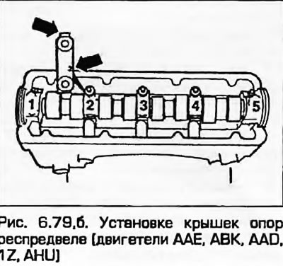 |
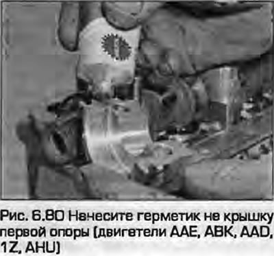
80. Lubricate the mating surfaces of cover No.1 with sealant and install covers No.1, 3 and 5 on the camshaft, gradually tightening their mounting nuts to the specified torque (Fig. 6.80).
All engines
81. If provided, install oil temperature and emergency pressure sensors in the cylinder head.
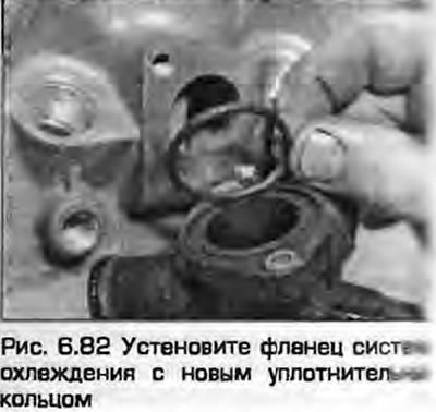
82. If provided, install the cooling system outlet flange together with a new gasket/O-ring (Fig. 6.82).
83. On diesel engines, install the injectors and glow plugs as described in chapters 4B and 5B.
84. Install the cylinder head as described in section A or B of this chapter. Install the camshaft sprocket as described in section A or B this chapter.