
Note: If only the crankshaft is removed, there is no need to remove the pistons and cylinder head. It is sufficient to repair the connecting rod bearing caps and move the connecting rods with pistons towards the head. It is highly recommended to use an engine mount stand for this operation.
As described in the chapter 2A or 2B, do the following:
- a) Remove the timing belt and crankshaft sprocket.
- b) Remove the clutch components and flywheel/faceplate.
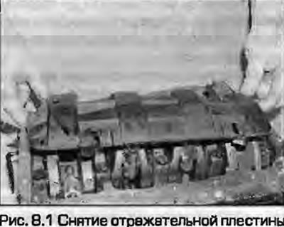
- c) Remove the pan, deflector plate (Fig. 8.1), oil pump and oil receiver.
- d) Remove the front and rear oil seal housings.
2. Remove the pistons with connecting rods or disconnect them from the crankshaft as described in paragraph 7 (see note above).
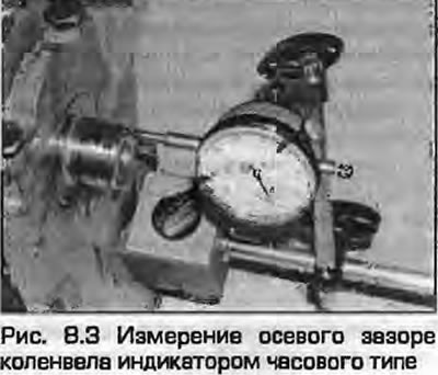
3. After removing the crankshaft, check its axial clearance using a dial indicator.
Note: This can only be done if the crankshaft is installed in the block and has the ability to move along the axis.
Set the dial indicator so that its measuring leg rests against the end of the crankshaft. Move the crankshaft as far as it will go and reset the indicator. Move the crankshaft to the other extreme position and measure the clearance (Fig. 8.3). Compare the result with Specifications. This will indicate the need to replace the thrust half rings.
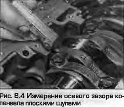
4. If there is no indicator, you can use a set of flat feeler gauges. The feeler gauges should be inserted between the side surface of the third crankpin and the half ring in the central support of the crankshaft (Fig. 8.4). Compare the results obtained with those given in Specifications.
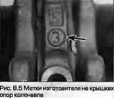
5. Identification marks must be cast on the crankshaft bearing caps. The caps are numbered starting from the timing belt side. If there are none, apply your own using a punch (Fig. 8.5).
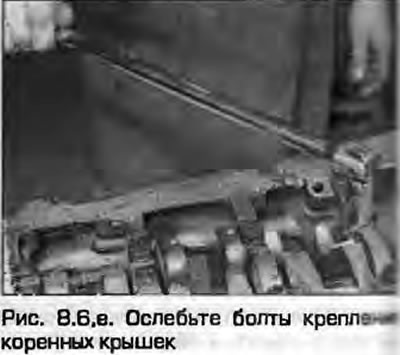
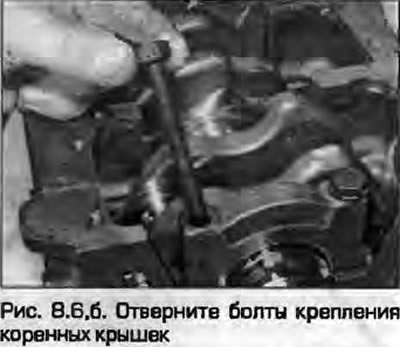
6. Loosen the bolts securing the support caps by half a turn per pass until you can unscrew them by hand and remove the caps together with the inserts (fig. 8.6, a, b). If the caps are tight, gently push them off with a brass or wooden mallet. If there are no numbers, apply your own, but do not scratch them.
 |
 |
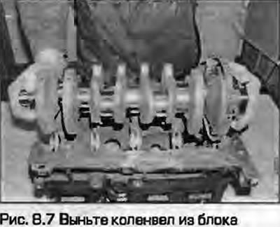
7. Carefully lift the crankshaft up from the inverted cylinder block (Fig. 8.7).
8. Remove the support half rings from both sides of the central support, remove the upper liners from the block. If you are going to install the liners back, put them together with the corresponding support covers.
9. After removing the liners, inspect the condition of the grooves for the protrusions (locks) of the liners, which allow the liners to be installed in only one position.
Examination
10. Wash the crankshaft with a suitable solvent and dry thoroughly. Flush the oil passages thoroughly to ensure that they are not clogged with dirt.
11. Carefully inspect the shaft journals. If there are obvious scratches, grooves or burrs, the shaft must be reground and new repair-size liners installed.
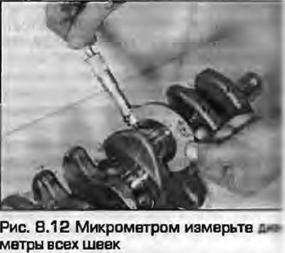
12. Using a micrometer, measure the diameter of all main journals (Fig. 8.12). Take several measurements at different points and angles to ensure that there is no ovality or taper. If the ovality or taper of the journals is outside the prescribed limits, Specifications, the shaft must be ground in a specialized auto repair shop.
13. Inspect the surfaces of the shaft journals under the seals. If the journals are heavily worn, the new seal may leak. The journals can be ground - ask the dealer's service center for advice.
14. Mount the shaft on the prisms and measure its runout on the central support journal using a dial indicator by "rolling" the shaft. When doing this, do not damage the journals resting on the prism. The maximum permissible runout is not prescribed by the manufacturers, however, a runout of 0.03 mm is usually considered acceptable. If the runout exceeds the permissible limit, the crankshaft may need to be replaced - consult your dealer or engine repair specialists for advice.
15. In paragraph 15 welding of crankshaft journals is described in detail.