Repair Chevrolet Repair Toyota Repair Honda Repair AvtoVAZ Repair Mercedes-Benz Repair BMW Repair Opel
Home  |  Contacts  |  Sitemap  |    
English Русский
Български
Беларускі
Український
Српски
Hrvatski
Română
Polski
Slovenský
Magyar
AudiManual.ru


  • AUDI 80
  • AUDI 100
  • AUDI A3
  • AUDI A4
  • AUDI A6
  • AUDI A8
  • AUDI Q
  • OTHER
  • ARTICLES
C4 (1990-1994) C4 (1990-1994, petrol) C3 (1982-1990) C3 (1982-1990, petrol) C3 (1982-1990, diesel)

Crankshaft — removal and inspection (Audi 100 C3)

  • Home
  • Audi 100
  • C3 (1982-1990, diesel)
  • Power unit
  • Engine removed
  • Crankshaft — removal and inspection
            0
Table of contents: Removal ↓ Inspection ↓

Removal


Note: If the pistons/connecting rods do not need to be rebuilt, there is no need to remove the cylinder head and pistons. It is only necessary to push the pistons far enough into the cylinders to clear the connecting rods from the crankshaft journals. It is highly recommended that a special stand designed for engine rebuilding be used.


1. Guided by Section 1A, do the following:
  • a) Remove the crankshaft sprocket and timing belt.
  • b) Remove the clutch components and flywheel or drive disc (depending on the model).
  • c) Remove the sump, its partition, oil pump and suction pipe.
  • d) Remove the rear crankshaft oil seal and its housing.

2. Remove the pistons and connecting rods or disconnect them from the crankshaft as described in Chapter 7 (see note above).

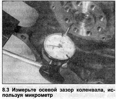
3. Turn the cylinder block over on the workbench and check the crankshaft end clearance as follows. Set the micrometer so that its probe is located on the crankshaft axis and touches the end of the shaft. Move the crankshaft to the stop in one direction and set the micrometer pointer to zero. Move the crankshaft to the stop in the opposite direction and record the resulting end clearance value (see illustration). Comparing the result with the figure stated in the Specifications will indicate whether new thrust washers are required.

3. Turn the cylinder block over on the workbench and check the crankshaft end clearance as follows.…


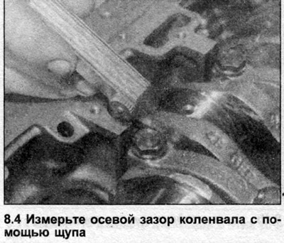
4. If a micrometer is not available, feeler gauges can be used. First, move the crankshaft as far as it will go against the flywheel, then select a feeler gauge whose thickness corresponds to the clearance between the counterweight of the crank pin of cylinder No.4 (5-cylinder engines) and the main bearing thrust washer (see illustration). Compare the results with the data given in the Specifications.


4. If a micrometer is not available, feeler gauges can be used. First, move the crankshaft as far…


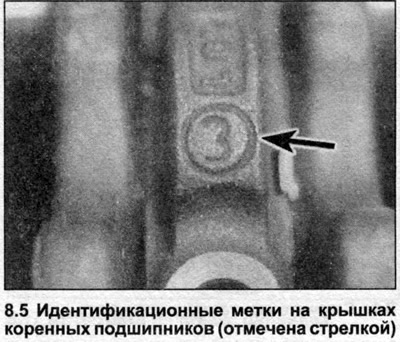
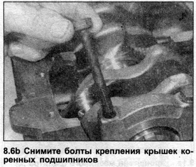
5. Pay attention to the marks on the main bearing caps. The number indicates the position of the cap in the crankcase, cap No.1 is located closest to the toothed drive belt (see illustration).

5. Pay attention to the marks on the main bearing caps. The number indicates the position of the…


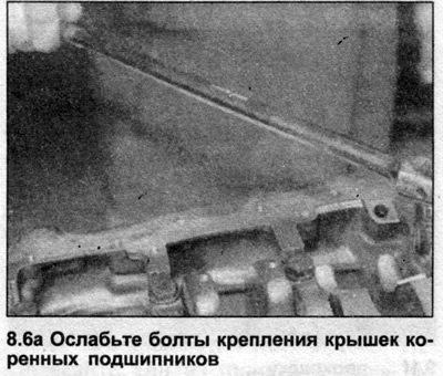
6. Loosen the main bearing cap bolts by turning them half a turn at a time and remove them (see illustrations). Tap the caps lightly with a mallet to loosen them from the crankcase. Remove the lower main bearing shells, securing them to the appropriate cap with adhesive tape for safekeeping. Mark them to avoid confusion, but do not scratch or nick them.

6. Loosen the main bearing cap bolts by turning them half a turn at a time and remove them (see…


6. Loosen the main bearing cap bolts by turning them half a turn at a time and remove them (see…


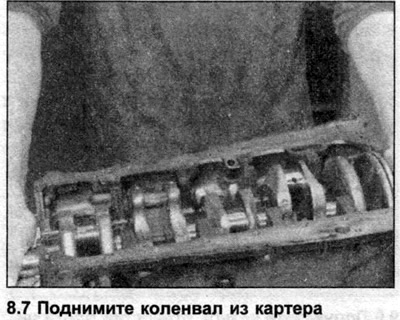
7. Carefully lift the crankshaft out of the crankcase, being careful not to displace the upper main bearing shells (see illustration).


7. Carefully lift the crankshaft out of the crankcase, being careful not to displace the upper main…


8. Remove the upper bearing shells from the crankcase and tape them to their respective bearing caps. Remove the two thrust washers from bearing #4 (5-cylinder engines).

9. Remove the bearing shells and note the recesses in the bearing caps and housing intended for the mounting protrusions of the bearing shells.

Inspection


10. Wash the crankshaft in a suitable solvent and allow it to dry. Clean the oil holes thoroughly, using a suitable brush if necessary.

11. Inspect the main and connecting rod bearing journals. If signs of uneven wear, cracks, scratches or pitting are found, have a specialist regrind the crankshaft and install it on the engine together with oversize liners.

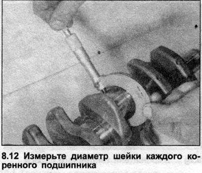
12. Using a micrometer, measure the journal diameter of each main bearing (see illustration). Measure several points around each journal to determine if it is out of round. Measure at the ends of the journal, near the counterweights, to determine if the journal is tapered. If such wear is detected, have the crankshaft reground by a specialist and purchase oversize bearings.

12. Using a micrometer, measure the journal diameter of each main bearing (see illustration).…


13. Check the seal contact areas on both ends of the crankshaft. If they are worn or damaged, the new seals will be damaged during engine assembly and will therefore leak. It may be possible to regrind the end of the shaft - contact your Audi dealer.


14. Measure the crankshaft runout by placing a micrometer probe on the 3rd and 4th main bearings (5-cylinder engines) and rotating the shaft on V-shaped supports. The maximum deviation of the micrometer needle corresponds to the runout. Do not damage the bearing journals and the contact surfaces with the seals during this procedure. Manufacturers do not specify the maximum permissible runout value, but it is approximately 0.03 mm. If the runout exceeds this value, consult an Audi dealer about replacing the crankshaft.

15. Inspection of main and connecting rod bearings is described in Chapter 10.
The article was checked by auto expert Nikita Rudakov
This article is available at russian, bulgarian, belarusian, ukrainian, serbian, croatian, romanian, polish, slovak, hungarian

Share information:
Previous articles
Audi 100 C3: Engine removed
Next articles

Piston/Connecting Rod Assemblies — Removal and Inspection
Cylinder head — disassembly, cleaning, inspection and assembly
Engine Overhaul — Preliminary Information
Engine — removal and installation
Cylinder block/crankcase — cleaning and inspection
Main and connecting rod bearings — inspection and selection of…
Engine assembly sequence
Crankshaft — installation and checking of working clearance


Similar articles on other Audi car models:
Crankshaft — removal, inspection and installation Audi 80 B3 (1986-1991, petrol)
Visual inspection of the gearbox for leaks Audi A3 Type 8L (1996-2003)
Crankshaft — Removal and Inspection Audi A4 B5 (1994-2001)
Clutch — removal, installation and inspection Audi A6 C5 Allroad (1999-2005)
Visual inspection of gearbox tightness Audi A8 D2 (1994-2002)
Removal and installation the drive disc and crankshaft seals Audi Q7 Typ 4L (2005-2015, diesel)
Removal and installation the crankshaft belt drive pulley Audi A2 (1999-2005)
Link to this page in different formats


Visitor comments

No comments yet


How much will 17 + 14 =


100(C4, 1990-1994) 
  • General information
  • User manual
  • Power unit
  • Engine repair
  • Ignition system
  • Fuel system (gasoline)
  • Fuel system (diesel)
  • Lubrication system
  • Cooling system
  • Exhaust system
  • Transmission
  • Clutch
  • Car gearbox
  • Drive shafts
  • Chassis
  • Car suspension
  • Steering
  • Wheels and tires
  • Brake system
  • Body
  • Ventilation and heating
  • Body repair
  • Electrical equipment
  • Power devices
  • Lighting and appliances
  • Electrical circuits
 
100(C4, 1990-1994, petrol) 
  • General information
  • Operation and maintenance
  • Power unit
  • Engine repair
  • Exhaust system
  • Cooling system
  • Supply system
  • Air filter
  • Mono-Motronic injection system
  • Digifant injection system
  • KE-III-Jetronic and KE-Motronic
  • MPI and MPFI injection system
  • Transmission
  • Clutch
  • Car gearbox
  • Chassis
  • Suspension and steering
  • Brake system
  • Wheels and tires
  • Body
  • Exterior
  • Interior
  • Electrical equipment
  • Fuses and relays
  • Power devices
  • Ignition system
  • Lighting and signaling
  • Equipment and devices
  • Electrical circuits
 
100(C3, 1982-1990) 
  • General information
  • User manual
  • Maintenance
  • Specifications
  • Power unit
  • Engines 4-cylinder
  • Engines 5-cylinder
  • Diesel engine
  • Cooling system
  • Power system (carburetor)
  • Power system (injector)
  • Fuel system (diesel)
  • Transistor ignition system
  • Electronic ignition system
  • Transmission
  • Clutch
  • 4 speed gearbox 014
  • 5 speed gearbox 013 and 093
  • 5 speed gearbox 016 and 012
  • Shift mechanism KP 016
  • Automatic transmission
  • Front wheel drive
  • Chassis
  • Front suspension
  • Rear suspension
  • Steering
  • Brake system
  • Body
  • Body elements
  • Electrical equipment
  • Lighting and appliances
  • Power devices
  • Electrical circuits
 
100(C3, 1982-1990, petrol) 
  • General information
  • Maintenance and operation
  • 4 cylinder engine
  • Engine repair
  • Cooling and lubrication system
  • Supply system
  • Ignition system
  • 5 cylinder engine
  • Engine repair
  • Cooling and lubrication system
  • Supply system
  • Ignition system
  • Transmission
  • Clutch and drive shafts
  • 4 speed gearbox 014
  • 5 speed gearbox 013 and 093
  • 5 speed gearbox 016 and 012
  • Automatic gearbox
  • Chassis
  • Steering
  • Front suspension
  • Rear suspension
  • Brake system
  • Body
  • Body elements
  • Doors, locks and windows
  • Body repair
  • Electrical equipment
  • Equipment and devices
  • Power devices
  • Electrical circuits
 
100(C3, 1982-1990, diesel) 
  • General information
  • User manual
  • Maintenance
  • Troubleshooting
  • Power unit
  • Engine in a car
  • Engine removed
  • Cooling system
  • Fuel system
  • Exhaust system
  • Starting and charging
  • Preheating
  • Transmission
  • Clutch
  • Mechanical gearbox
  • Automatic gearbox
  • Drive shafts
  • Chassis
  • Brake system
  • Suspension
  • Steering
  • Body
  • Exterior
  • Interior
  • Electrical equipment
  • Equipment and devices
  • Electrical circuits
 
AudiManual.ru © 2017-2026 · Mobile version · Feedback · Sitemap: EN BG BY UA RS HR RO PL SK HU · Site search · News and articles
80 B2 · 80 B3 petrol · 80 B3 · 80 B4 · 100 C3 diesel · 100 C3 petrol · 100 C3 · 100 C4 petrol · 100 C4 · A3 Type 8L · A4 B5 petrol · A4 B5 · A4 B6 petrol · A4 B6 · A4 B7 · A4 B8 · A6 C4 · A6 C5 · A6 C5 Allroad · A8 D2 · Q5 Type 8R · Q7 Typ 4L · Audi A2 ·
This site uses cookies 🍪. Click the button to accept this fact.