
Table of contents: Removal ↓ Installation ↓
Removal
1. Park the car on a firm, level surface.
2. See. Section 11 and remove the hood. On models with 5-cylinder engines, this is not necessary, since the radiator and the upper cross member of its frame will be removed and the engine will only need to be slightly raised to separate it from the subframe.
3. Disconnect the negative cable from the battery and move it away from the terminal (see Section 4A).
Note: If your car's radio is coded, make sure you have the key code before disconnecting the battery.
4. Do the following:
- a) If the engine needs to be disassembled, drain the engine oil.
- b) Drain the cooling system.
5. Apply the handbrake, then jack up the front of the car and support it on axle stands.
6. Unscrew the screws and remove the lower engine shield.
7. Remove the front bumper and the upper radiator frame cross member (see Section 11). Also remove the fan unit with the heat-viscous coupling (Section 2).
8. On models without air conditioning, remove the radiator (see Section 2). To do this, detach the transmission fluid cooler from it, move it to the side and tie it to the body with a piece of twine.
9. On models with air conditioning, unclip the trim from the right side of the radiator, then remove the radiator mounting bolts. Remove the right radiator bracket bolts. Remove the mounting bolts and slide the radiator forward. There is a special Audi bracket designed to hold the radiator away from the engine, but a metal strip or block of wood will work just fine.
10. Working underneath the vehicle, remove the bolts from the undershield support crossmember, which is located under the rear of the transmission on some models. On 3D engines, remove the front mount and torque rod bolts as described in Section 1A.
11. Working at the rear of the engine, remove the fuel pump drive belt cover bolts.
12. Remove the air cleaner assembly as described in Section 3A.
13. Remove the air hoses running between the air cooler and the intake manifold and between the air cooler and the turbo generator.
14. Disconnect the vacuum hoses from the exhaust gas recirculation (EGR) valve and intake manifold.
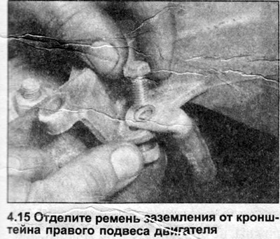
15. Remove the ground strap from the right engine mount bracket. Mark this strap to avoid confusion with the starter rope (see illustration).
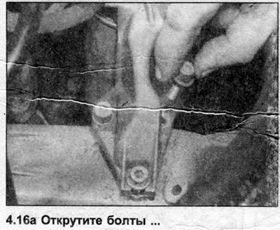
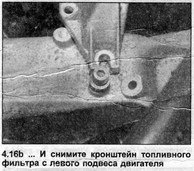
16. Unscrew the fuel filter bracket bolts from the left engine mount. The front bolt only needs to be loosened, since the bracket has a slot in this place, not a hole (see illustrations).
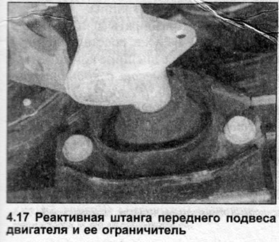
17. Remove the front suspension reaction rod and its stop from the engine and crossmember as described in Section 1A (see illustration).
18. Disconnect the cooling system hoses from the radiator, expansion tank and cylinder head.
19. Disconnect the wiring from the generator and remove the ground strap.
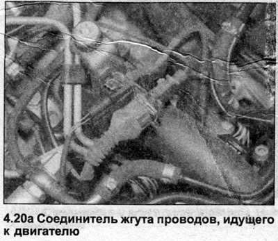
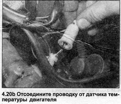
20. Remember how the engine wiring runs, then methodically disconnect the wires, marking the location of each one (see illustrations). It is necessary to disconnect the electrical wiring going to the following components (note that depending on the reason for removing the engine, some electrical wiring may remain connected (in the partition on the right):
- a) Exhaust gas recirculation valve;
- b) Air flow meter;
- c) Boost pressure control valve;
- d) Intake manifold temperature sensor;
- e) Glow plugs.
21. Disconnect the fuel supply and return hoses from the fuel pump and plug the ends of the hoses and the openings in the pump.
22. Disconnect the gas pedal cable as described in Section 3A.
23. Disconnect the vacuum hoses (including the brake booster vacuum hose, which must be separated from the vacuum pump), marking them.
24. Disconnect the hoses from the heater matrix in the bulkhead.
25. On manual transmission models, disconnect the wiring from the reverse light switch on the transmission. Also disconnect the wiring from the speedometer sensor.
26. Remove the auxiliary drive belts.
27. On models equipped with air conditioning, remove the compressor from the engine without disconnecting the refrigerant pipes. Move the compressor to the side and tie it to the wall of the engine compartment.
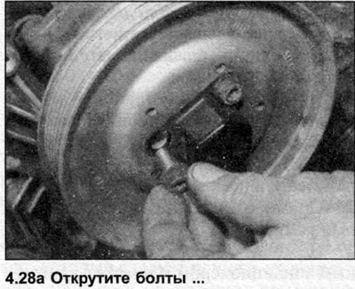
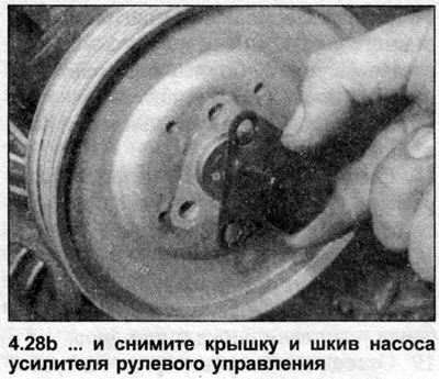
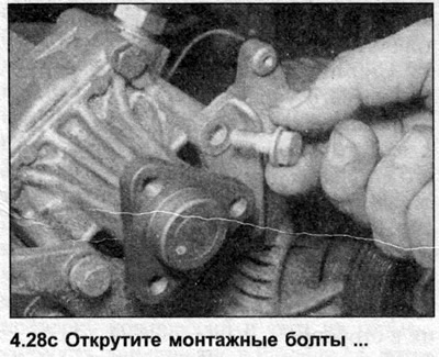
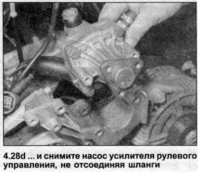
28. Remove the power steering pump from the engine without disconnecting the hydraulic pipes (see Section 10). Move the pump to the side and tie it to the wall of the engine compartment (see illustrations).
29. On models with automatic transmission, remove the bolts from the bracket securing the transmission fluid pipes to the oil pan and move them to the side.
30. Remove the starter as described in Section 4A.
31. On models with automatic transmission, loosen the three bolts securing the torque converter to the drive plate by turning the crankshaft to alternately guide the bolts into the starter opening.
32. Where fitted, remove the cover from the right drive shaft. Disconnect the exhaust outlet pipe and catalytic converter from the exhaust manifold. Remove the bolts and separate the outlet pipe from the transmission bracket.
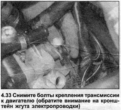
33. Remove the bolts holding the transmission to the engine, but leave the top bolt in place for now, just loose enough to remove by hand. Note that on some models the top left bolt also holds the wiring harness bracket (see illustration).
34. Attach a winch to the engine and lift it slightly to transfer the weight of the engine from the hangers to the lifting device. Make sure that the engine remains level, which is very important to separate it from the transmission.
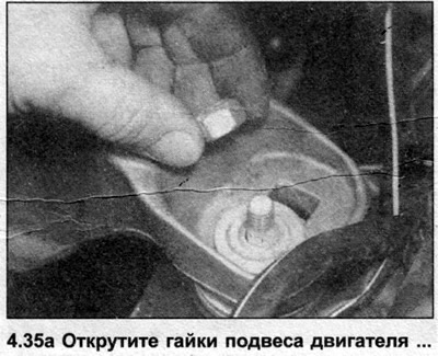
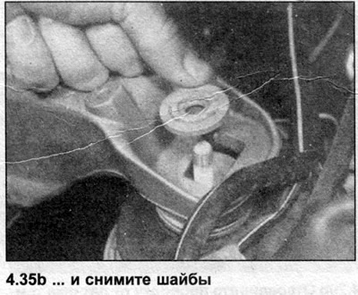
35. Unscrew the nuts of the left and right engine mounts (see illustrations).
36. Support the transmission with a jack, placing a piece of board between them.
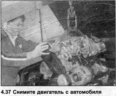
37. Remove the remaining transmission mounting bolt, then have an assistant slide the engine forward, keeping it level the entire time, and lower it to the ground (see illustration). On automatic transmission models, make sure the torque converter remains in the transmission, fully engaged with the input shaft. Remove the dowel pins from the rear of the cylinder block if they are loose.
38. On manual transmission models, remove the clutch as described in Section 5.
Installation
39. Refit in the reverse order. On manual transmission models, pre-lubricate the input shaft grooves with a small amount of high temperature grease. Lightly lubricate the contact surface of the release bearing, but do not apply grease to its guide sleeve. Ensure that all engine and transmission brackets are mounted straight and tighten all nuts and bolts to the torque specified in the Specifications. Install and, where necessary, adjust all engine-related components and systems as described in the relevant Sections. Ensure that the engine is filled with oil and that the cooling system is refilled before starting the engine.