
Table of contents: Removal ↓ Inspection ↓
Removal
1. See. Section 1A, and remove the cylinder head, flywheel, oil pan and its partition, oil pump and its intake pipe.
2. If a ridge caused by carbon deposits or wear is visible on the top of any of the cylinders, remove it with a scraper or reamer accordingly to avoid damaging the piston during removal.
3. Using feeler gauges, measure the clearance between the connecting rods and the bearing surface of the crankshaft counterweight and record the results.
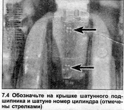
4. Rotate the crankshaft to bring piston #1 to bottom dead center. If not numbered by the manufacturer, use a hammer and punch or paint to mark the cylinder number on each connecting rod bearing cap and on the connecting rod itself (see illustration). Mark the orientation of the bearing caps relative to the connecting rod to ensure proper assembly.
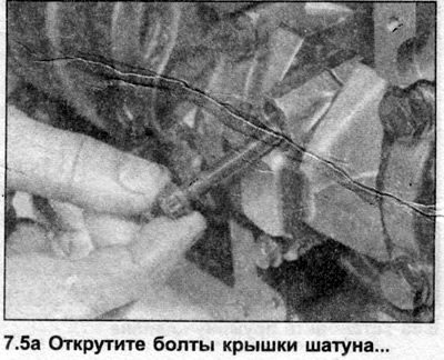
5. Loosen the bearing cap nuts/bolts by turning them half a turn at a time and remove the cap (see illustrations). Remove the lower bearing shell from the shaft and tape it to the cover to avoid losing it. Note that unless the shells require replacement, they must be installed on the same connecting rod.

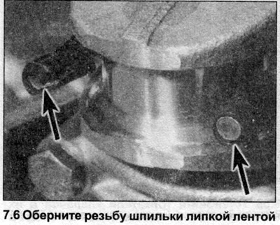
6. Where bearing caps are secured with nuts, wrap the threaded ends of the studs with masking tape to prevent them from scratching the crankshaft journals and cylinders when removing the pistons (see illustration).
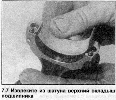
7. Push the piston up out of the cylinder using the handle of a hammer. Remove the upper bearing shell and tape it to the connecting rod for safekeeping (see illustration). On engines equipped with piston cooling oil jets (installed at the bottom of the cylinders), make sure that the connecting rod does not damage the jet when removing the piston.
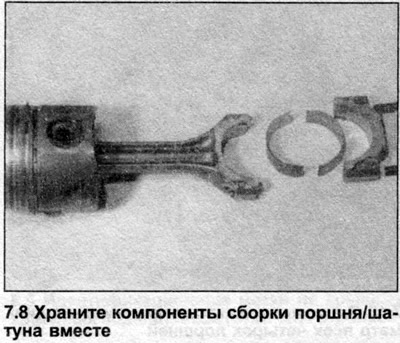
8. On 5-cylinder engines, rotate the crankshaft to bring piston #2 to bottom dead center, then remove the piston. Remove pistons #4, 5, and 3 in the same manner. Keep components from the same cylinder together to avoid mixing them up during installation (see illustration).
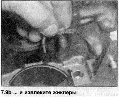
9. Where present, remove the mounting screws and extract the piston cooling oil jets from the cylinder base (see illustrations).

Inspection
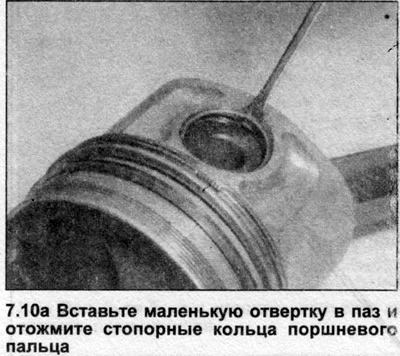
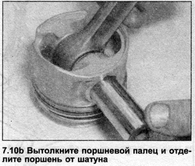
10. Insert a small flat-head screwdriver into the existing slot and press out the piston pin retaining rings. Push out the piston pin and separate the piston from the connecting rod (see illustrations). Discard the retaining rings - they are subject to replacement. If the pin cannot be removed, heat the piston to 60°C with hot water.
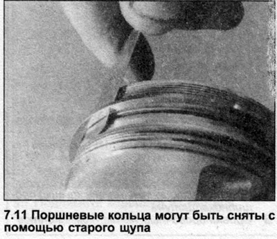
11. Before you begin inspecting the pistons, you need to remove the piston rings from them using a special tool or an old feeler gauge. First remove the top piston rings by gently squeezing them apart. Be careful not to scratch the piston with the ends of the ring. The rings are fragile and will break if you squeeze them too hard. In addition, they are very sharp - protect your hands with gloves. Throw away the rings, they are subject to replacement (see illustration).
12. Remove carbon deposits from the piston ring grooves using a piece of an old ring (break the ring in half, working carefully so as not to cut your fingers). Be careful not to remove any metal along with the carbon deposits or scratch the walls of the grooves.
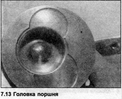
13. Clean off the main carbon deposits from the piston head (see illustration). Then clean it with a wire brush or fine sandpaper. Be careful not to scratch the piston.
14. After removing the carbon deposits, clean the pistons and connecting rods with kerosene or a suitable solvent and dry them thoroughly. Make sure that the oil return holes in the ring grooves are not clogged.
15. Inspect the pistons for damage and signs of excessive wear. Normal piston wear is manifested by uniform vertical wear of its axial pressure surfaces and a slight play of the upper ring in the groove. If signs of wear other than those indicated are detected, determine whether the component is suitable for further use and what is the cause of the wear.
16. Scoring or scratching of the piston skirt may indicate that the engine has overheated due to inadequate cooling or lubrication. Burnt spots on the piston walls indicate that blow-by has occurred, possibly caused by worn cylinder walls or piston rings. Dimples or burnt spots on the piston crown usually indicate that the engine is pre-igniting or detonating. In severe cases, the piston crown may even melt. Pitting of the piston crown indicates that coolant has leaked into the combustion chamber. If any of the above damage is found, identify the causes and correct them, otherwise the damage will occur again.
17. Check the pistons, connecting rods, piston pins and bearing caps for cracks. Lay the connecting rods on a flat surface and visually inspect them for deformation. If in doubt, have a specialist take precise measurements using appropriate instruments. Inspect the big-end bearing for cracks and signs of wear.
18. Using a micrometer, measure the diameter of all four pistons at 10 mm from the base of the skirt along an axis perpendicular to the axis of the piston pin (see illustration). Compare the measurement results with the data given in Specifications. If the piston diameter is outside the tolerance range, replace the piston.
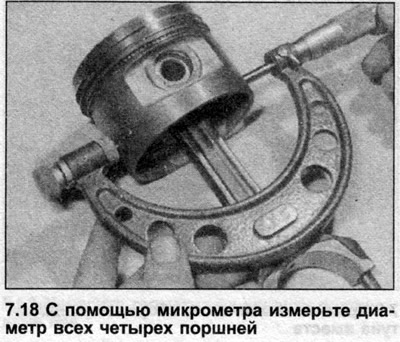
Note: If the cylinder block was bored out during a previous overhaul, oversize pistons may have been installed. Record all measurements, as they will be used to determine piston clearances after measuring the cylinder diameter (see further in this Section).
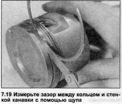
19. Install a new piston ring into the appropriate groove and measure the gap between the ring and the groove wall using a feeler gauge (see illustration). Please note that the rings have different widths, do not mix up the grooves. Compare the measurement results with the data given in Specifications. If the clearance value is outside the permissible tolerances, replace the piston.
20. Inspect the big-end bearing and piston pin for damage and signs of wear. If wear is excessive, the piston pin must be replaced and a new bushing installed in the connecting rod. This work should be entrusted to a specialist.
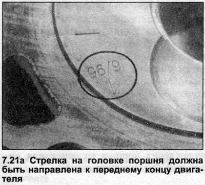
21. Connect the piston to the connecting rod, observing their correct mutual arrangement. An arrow is applied to the piston head (may be obscured by carbon deposits) (see illustration), which should be directed towards the front end of the engine. The connecting rod and bearing cap have recesses-marks located near their contact surfaces, which should be facing the same direction as the arrow on the piston head (see illustration).
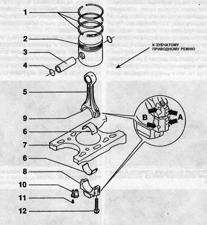
7.21b Piston assembly
1 - Piston rings
2 - Piston
3 - Piston pin
4 — Retaining ring
5 — Connecting rod
6 — Connecting rod bearing shell
7 — Upper part of the cylinder block
8 — Connecting rod bearing cap
9 — Mounting pin (not on all models)
10 — Piston cooling oil jet (not on all models)
11 — Oil jet mounting screw
12 — Connecting rod bearing cap bolts
A - Bearing cap/connecting rod identification marks
B — Reference marks of components
Note: On some engines the connecting rod ends are equipped with dowel pins that fit into holes in the bearing caps. The dowel pins must be installed in the connecting rods, not the caps.
22. Lubricate the piston pin and connecting rod small-end bushing with clean engine oil. Push the pin into the piston through the connecting rod small-end. Install two new snap rings on both ends of the piston pin. Repeat this step on the remaining pistons.