
Table of contents: Removal ↓ Installation/Tightening Torques ↓
Removal
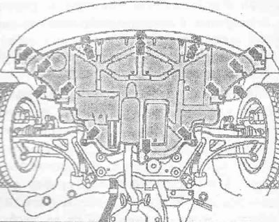
To remove the 1.4 l engine on the Audi A2, the following preparatory operations must be performed: the noise-insulating casing must be removed.
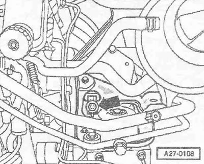
In the center of the cylinder block lug, make a 6.5 mm "arrow" hole and cut a thread. On the engine bracket, make a 12 mm "arrow" hole.
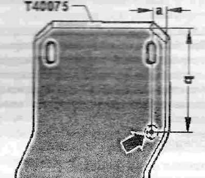
Distance "a" = 12 mm. Size "b" = 73 mm.
Instructions. Remove the engine together with the gearbox downwards. When reassembling, install all binders in the places where they were originally installed. Risk of damage to electronic components when disconnecting battery terminals. Follow the instructions when disconnecting battery terminals. The battery is located in a special compartment in the trunk.
Turn off the ignition and remove the ignition key. Loosen the nut a few turns and remove the pole tip "arrow" of the ground cable from the battery terminal.
Remove the engine hood.
Warning! Risk of burns from hot steam and hot coolant. When the engine is warm, the cooling system is under excess pressure. To relieve excess pressure, place a rag around the coolant expansion tank cap and carefully open it.
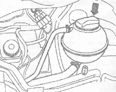
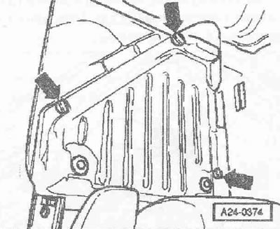
Open the "arrow" cap of the coolant expansion tank. Remove the front wheels. Remove the noise-insulating casing, loosen the "arrow" fasteners for this.
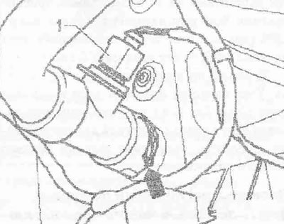
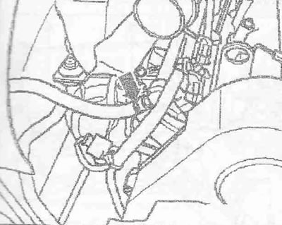
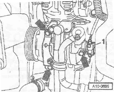
Install the tray for the service cranes "VAS 6208" under the engine. Disconnect the plug connector "1" of the coolant sensor at the outlet of the radiator "C-83". Disconnect the lower coolant hose "arrow" from the radiator, for which lift the clamp; drain the coolant.
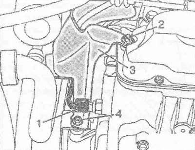
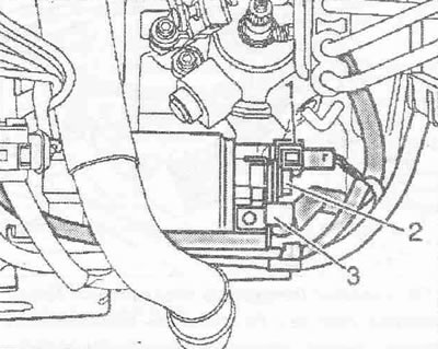
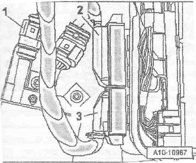
Unscrew nuts "2" and "4" to protect starter "3". Disconnect connector "1".
Remove the electromagnetic valve 1 of the absorber "N80" "pos. 2" with the bracket from the air duct. Disconnect the connector "3", remove the hose and lay it freely "1".
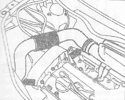
Remove the air duct by loosening the spring clamps with hose clamp pliers "V.A.G. 1921" "arrows".
Remove the fuel supply hose "arrow".
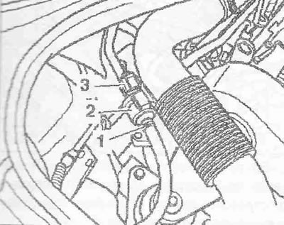
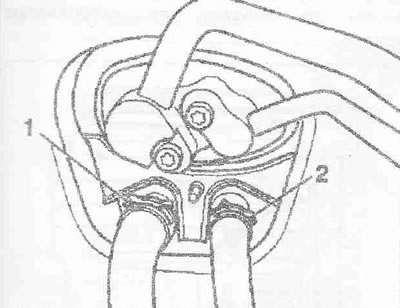
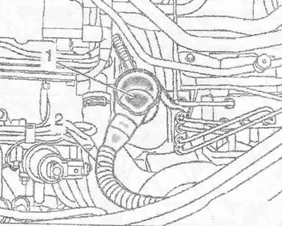
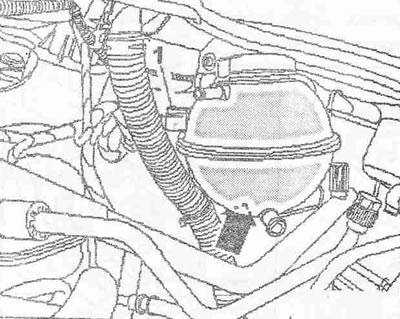
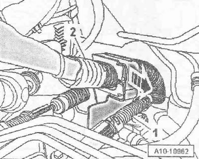
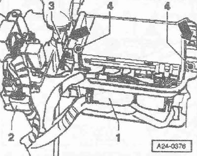
Mark the coolant supply hose "1" and the return hose "2" to the heater heat exchanger and remove from the engine shield.
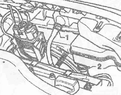
Remove the oil dipstick from the guide tube. Remove the guide tube "1" of the oil dipstick; to do this, press the locking buttons. Remove the oil filler tube "2" from the oil filler tank.
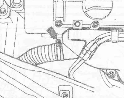
Remove the intake air preheating hose from the "arrow" heat shield.
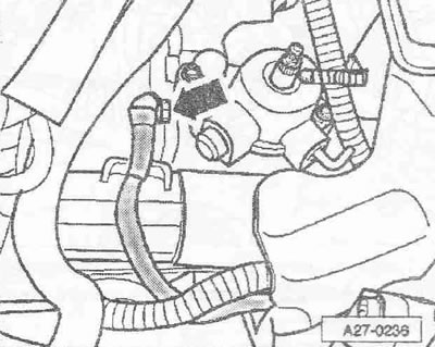
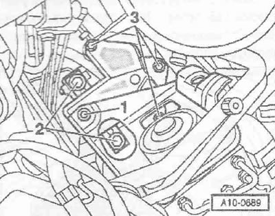
Unscrew the water collector "1" and put it aside together with the connected drain hose "2".
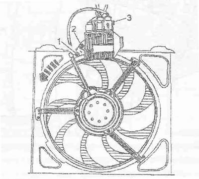
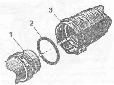
Disconnect connector "3" on radiator fan control unit J293-. Unscrew bolt "2" and remove radiator fan control unit "J293". Unscrew lock screw "1". Turn lock ring counterclockwise "arrow" and remove radiator fan "V7" together with lock ring.
Remove coolant hose "2". Remove coolant hose "1" from the radiator by lifting the clamp.
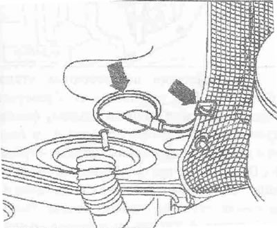
Remove the coolant hoses "arrows" from the coolant expansion tank and place the coolant hose freely on top.
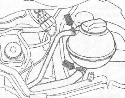
Disconnect the plug connector "1" of the low coolant level indicator sensor "F66". Unscrew the nut "arrow" and remove the coolant expansion tank.
Caution! Risk of damage to cable locks. Do not remove cable locks from the shift rod lever and intermediate lever. Removed cable locks must be replaced.
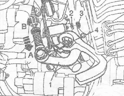
Remove cap "3" above the lock washer. Remove lock washer "2" from the intermediate lever. Unlock the selector and shift cable lock as described below: pull the safety mechanism on the shift drive cable "arrow A" forward as far as it will go. Turn the movable sleeve "arrow B" as far as it will go and lock it. Unscrew nut "4" and remove lever "1" of the gearshift rod. Unscrew nut "arrow" and lay the ground wire freely.
Unscrew the "arrow" nut and lift up the starter protection cover.
Unscrew nut "2", holding the traction relay wires to protect them from damage. Remove wire B+. Remove anti-rotation stop "3".
Place the B+ wire loosely on the holder "1". Place the engine wiring harness "2" loosely on the support "arrow".
Unscrew the "arrow" bolts and remove the support for the shift rods from the gearbox.
Unscrew the "arrow" bolts, remove the clutch slave cylinder and put it aside, do not open the pipeline system.
Caution! Risk of damage to the clutch slave cylinder. Do not press the clutch pedal when the clutch slave cylinder is removed.
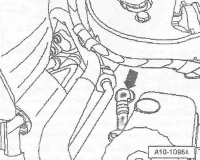
Remove the vacuum line "arrow" from the brake booster.
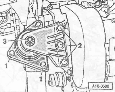
Instructions: Unscrew nut "3" only after replacing the engine mount.
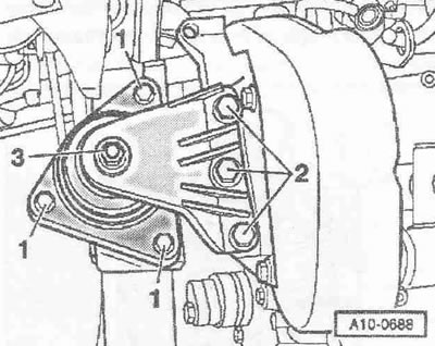
Unscrew bolts "1" and "2" by approximately 2 turns.
Unscrew bolts "2" on the gearbox cushion by about 2 turns. Lift the carpet in the footwell on the driver's side and remove the "arrow" trim.
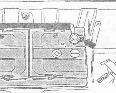
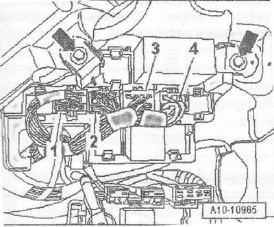
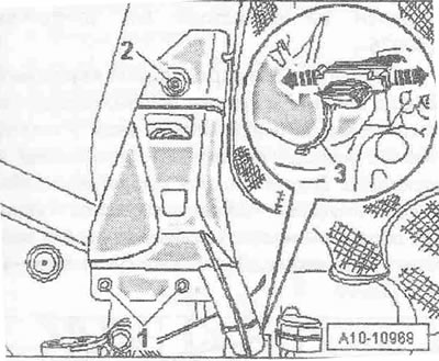
Remove the fuse box "3" from the relay box. Unscrew the bolt and nut "arrows" and carefully pull out the control unit bracket. Carefully pull out the engine control unit "1", to do this, unlock the clamps 4-, as shown in the figure.
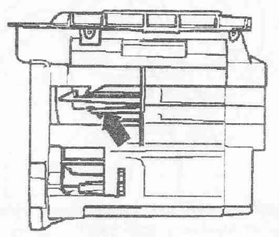
Instructions. The figure shows the control unit bracket, side view. To unlock the control unit, press the clamps "in the direction of the arrow".
Disconnect connectors "1...4" and lay the wiring harness loosely. Unscrew the "arrow" bolts and put the relay unit aside.
Disconnect connectors "2" and "3" from the engine control unit. Release the wiring harness.
Unscrew bolts "1" and "2". Cut cable tie "3", unlock "arrow" clamps and remove wiring. Route engine wiring harness on body.
Remove the wire for the lambda probe after the catalytic converter "G130" from the rubber tip "arrow to the left" and unclip it from the heat shield arrow to the right. Unscrew 2 bolts for the heat shield and freely lay the wire for the lambda probe after the catalytic converter "G130".
Unscrew the "arrow" bolts and remove the heat shield from the rear.
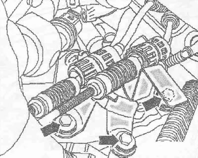
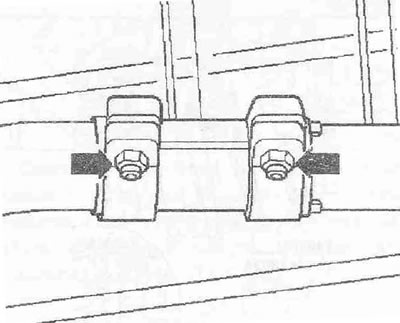
Loosen the threaded connections "arrows" for the clamping sleeve.
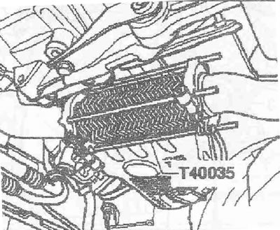
Protect the detachable element from bending with the "T40035" clamp.
Unscrew the bolts "arrows" securing the exhaust pipe to the exhaust manifold. Remove the exhaust pipe with the catalytic converter and resonator from the mounting cables and set aside.
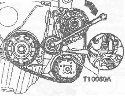
Caution! Risk of destruction if the used poly V-belt is rotated in the opposite direction. Before removing the poly V-belt, mark the direction of rotation on it with chalk or a felt-tip pen.
To loosen the poly V-belt, turn the tensioner with a ring spanner clockwise "arrow". Secure the poly V-belt tensioner with the locking pin "T10060 A" and remove the poly V-belt.
Disconnect connector "1" of the electromagnetic clutch on the air conditioning compressor. Unscrew the "arrow" bolts of the air conditioning compressor.
Caution! Risk of damage to the cooling system hoses and lines. Do not twist, bend or deform the refrigerant lines and hoses.
Tie the air conditioning compressor with the refrigerant hoses connected to the radiator frame from above. Unscrew the "arrow" bolts and remove the heat shield of the right drive shaft.
Unscrew the left and right articulated shafts from the shafts with the gearbox flange.
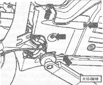
Unscrew the "arrow" bolts and remove the lower support of the power unit.
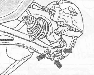
Unscrew the left and right "arrow" nuts of the axle joint. If present, unscrew the nut on the holder of the front left ground clearance sensor "G78". Hang the axle joints from the transverse levers.
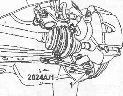
Turn the left shock absorber strut outward and support it with the extension "2024 A" as shown in the figure. Secure the ball joint with the nut "1".
Rotate the right joint shaft forward. First, move the power unit forward. Attach the joint shaft to the side member "arrow". When removing, be careful not to damage the surface of the joint shaft.
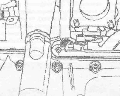
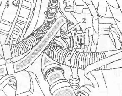
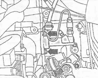
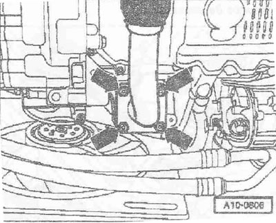
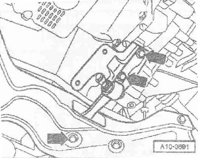
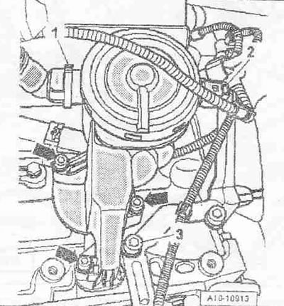
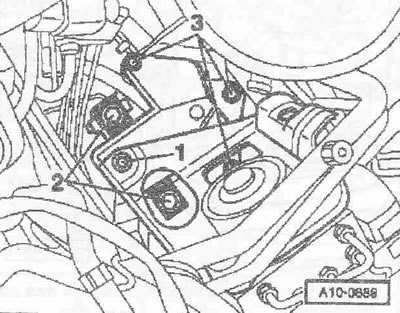
Disconnect connector "2". Remove air duct hose "1". To do this, press the locking buttons. Unscrew the bolts "arrows" and remove the crankcase ventilation system pressure reducing valve from the cylinder block. Unscrew bolt "3" for the bracket.
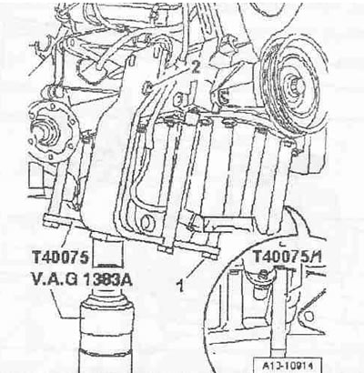
Check if the T40075 engine bracket and cylinder block are prepared for removing the engine. Unscrew bolt "1" for support "T40075/1" on the T40075 engine bracket. Screw support "T40075/1" into a new threaded hole. Install the T40075 engine bracket on the engine, as shown in the figure, and screw together with bolt "1" with support "T40075/1". Tighten the T40075 engine bracket at the rear of the engine with an M10x25 bolt - with a washer to a torque of 20 Nm on the cylinder block. Place the T40075 engine bracket on the VAG 1383 A tilting device. Raise the engine slightly with the VAG 1383 A tilting device. Unscrew nut "3" only after replacing the engine mount. Unscrew bolts "1" and "2".
Unscrew bolts "2" on the gearbox mount.
Instructions: Check that all hoses and wires between the engine, body and gearbox are disconnected. The power unit should be lowered with extreme care to avoid damage. Pay particular attention to the shift cables and engine wiring harness.
Slowly lower the engine/gearbox unit using the VAG 1383 A tilting device.
Installation/Tightening Torques
Instructions. The tightening torques given are valid for lightly lubricated, phosphated or oxidized nuts and bolts. Additional lubricants, such as oils, are permitted, except for graphite-containing ones. Do not use degreased parts. The tightening torque tolerance is ±15%.
| Mb | 10 |
| M7 | 15 |
| MV | 22 |
| M10 | 40 |
| M12 | 65 |