
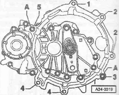
| 1, 3 | M12xb5 | 80 |
| 21) | M12X135 | 80 |
| 4 | M10x50 | 40 |
| 5 | M12x80 | 80 |
| A | Centering bushings | |
1) Additionally, a starter for the gearbox.
Installation is in the reverse order, taking into account the following: the engine is installed on the engine retainer "T40075".
Instructions. Replace self-locking nuts and screws. Replace bolts/screws tightened to a certain angle, as well as sealing rings, lip seals and gaskets. Secure all hose connections with clamps of the appropriate series. When reassembling, install all binders in the places where they were originally installed.
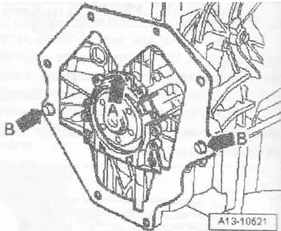
If the engine and gearbox centering bushings are missing, install them. Check whether the intermediate shield "arrow A" is connected to the sealing flange and whether it is mounted on the centering bushings "arrows B". Clean the drive shaft gearing and the hub gearing from dirt and corrosion, apply a very thin layer of "G 000 100" grease to the gearing. Be sure to remove excess grease. Check the clutch release bearing for wear, replace if necessary. Check the seal for the right shaft with flange for leaks; replace if necessary. Bolt the gearbox to the engine. Install the right shaft with flange. Install the parterre. Install the bracket for the exhaust manifold. When lifting the engine/gearbox unit, watch the gearshift drive cable and engine wiring harness. Install the power unit in the body. Install the gearbox mount. Install the engine mount. Unscrew the "T40075" engine bracket from the engine. Install the crankcase ventilation pressure reducing valve. Install the pendulum support. Install the drive shafts and ball joints. Install the drive shaft heat shield. Install the air conditioning compressor. Install the poly V-belt. Install the exhaust pipe with the catalytic converter and resonator. With the clutch slave cylinder removed, do not press the clutch pedal. Install the clutch slave cylinder. Adopt and adjust the shift cable drive and the selector cable drive.
Install the radiator fan. Install the support with the guide tube for the oil dipstick and the oil filler tube. Follow the instructions after connecting the battery terminals. Check the oil level. Risk of damage to the control units due to overvoltage. Do not use a charger to start the engine! Fill with coolant.
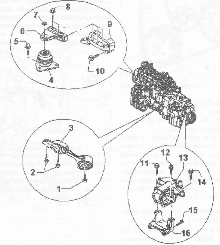
Engine and gearbox mounting elements:
1. Bolt 50 Nm
2. Bolts, replace. 60 Nm + 90°
3. Lower support of the power unit
4. Engine support
5. Bolt, replace. 23 Nm + 90°
6. Bracket
7. Nut, may only be removed to replace engine mount "pos. 4". Replace. 40 Nm + 90°
8. Bolt, replace. 60 Nm + 90°
9. Engine support
10. Bolt. 50 Nm
11/12. Bolt
13. Gearbox cushion
14/15. Bolt
16. KP support
[The original publication in its entirety is posted on the website: audimanual]