
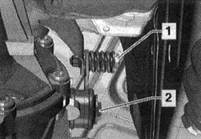
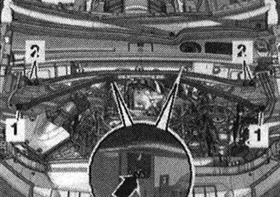
Carefully remove the motor cover. compartment -in the direction of the arrow- from the mounting bolts. Do not remove the engine cover jerkily or to the side. Remove noise insulation panels -1- and -2-. Remove sound insulation on the right and left -1- in the wheel arch.
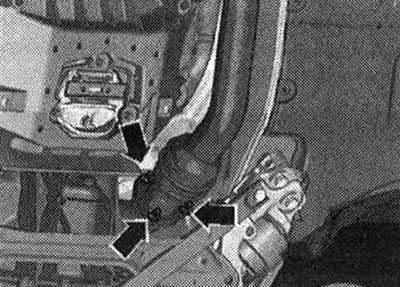
Unscrew the exhaust pipe nuts -arrows-.
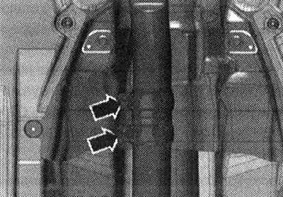
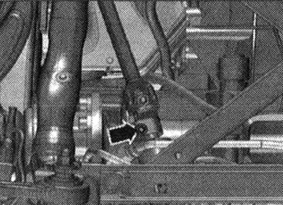
Disconnect the exhaust system at the clamping bush -arrows- and remove the exhaust pipe.
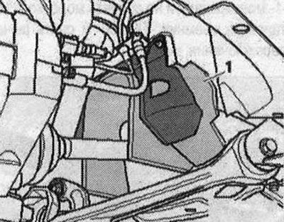
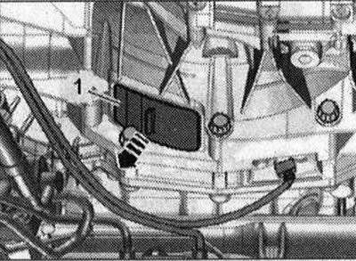
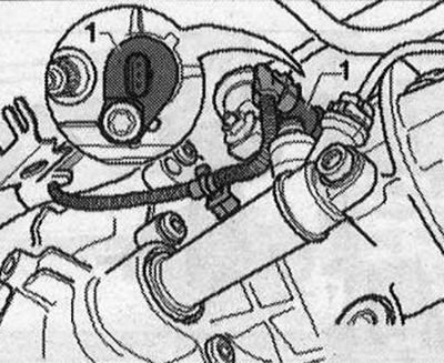
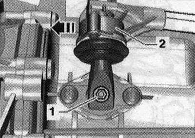
Unscrew screw connection -1-.
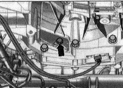
Remove the spacer. Remove the air housing. filter.
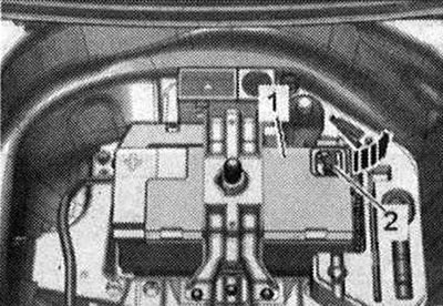
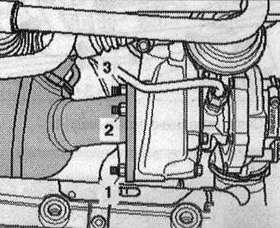
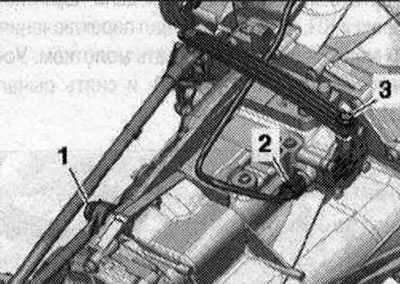
Unscrew the nuts -1,2,3- of the turbocharger and tie up the filter.
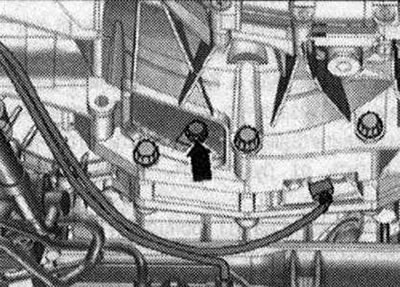
Unscrew bolts -2...6- of the engine/gearbox connection. Bolts -3- and -5- additionally secure the line brackets. Attach these brackets to the engine. Bolt -2 secures the starter to the gearbox. There is a spacer bush -arrow- between the starter and gearbox.
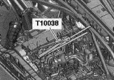
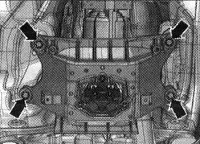
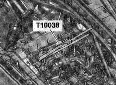
Install the brace and attach it with the tensioning belt -T10038- to the engine eye as shown in the illustration. Tighten the tension belt.
Risk of damage to the coiled Airbag spring. Disconnect the universal joint from the steering gear only with the front wheels mounted straight. Do not change the position of the steering wheel and steering gear any more; to do this, if necessary, secure the steering wheel with electrical tape. Unscrew the bolt -arrow- for the cardan joint. Press the steering gear universal joint out and push it all the way up.

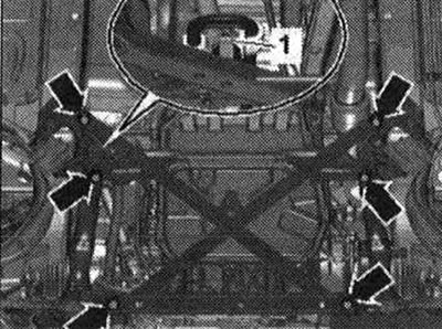
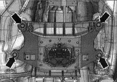
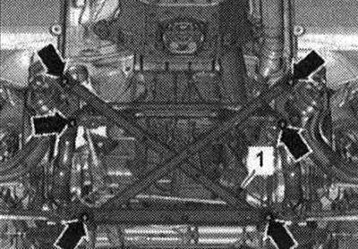
Unscrew the nut -1- of the hydraulic oil pressure line of the power steering. Risk of damage to chassis parts. Never lower the vehicle onto its wheels unless the subframe support, steering gear or subframe cross joint are properly installed. Supporting the vehicle on a subframe or subframe struts (for example, on a mobile jack) not allowed! Unscrew the bolts -arrows- and remove the subframe spacer.
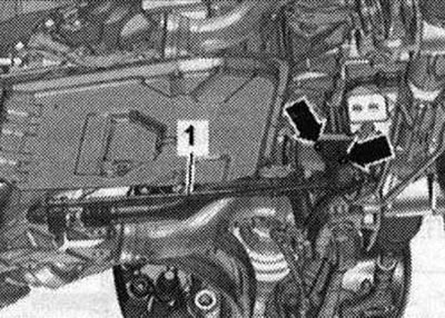
Engage 6th gear, to do this, remove the shift shaft -1- and shift the gearbox lever -2- forward in the -direction of the arrow-.
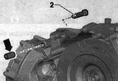
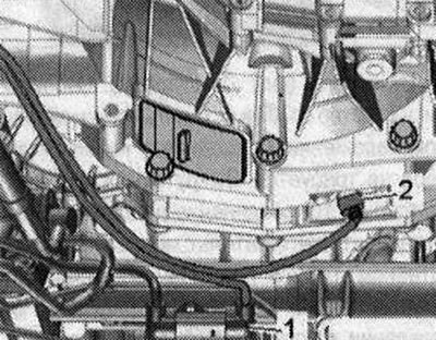
If present, disconnect electrical connector -2- from engine speed sender -G28- and free electrical connection. wire to the gearbox. -Pos. 1- do not take into account.
Remove trim -1- under gearbox -arrow-.
Unscrew the 3 bolts -arrow- of the driven disc; to do this, rotate the crankshaft through 120°in the direction of engine rotation.
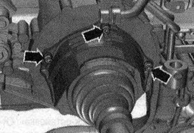
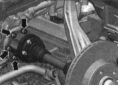
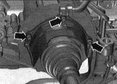
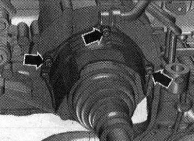
Unscrew the bolts -arrows- and remove the heat shield for the right drive shaft.
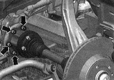
Unscrew the left and right drive shafts from the shafts with the gearbox flange.
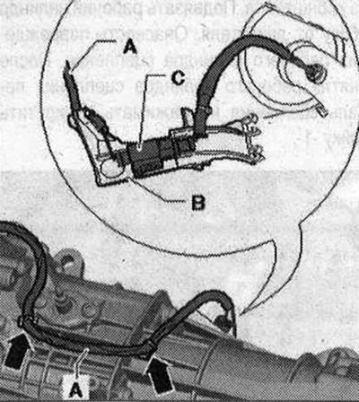
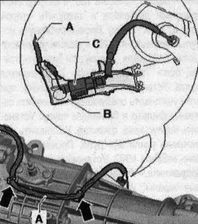
Compress email wire -A- to gearbox -arrows-. Remove bracket -B- with connector -C- for exhaust temperature sender 4 -G648- from gearbox and secure at top.
Remove bolts -1- and -3-.
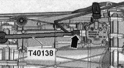
Disconnect electrical connector -arrow-for gear detection sensor -F208- using puller -T40138- and free electrical cable.
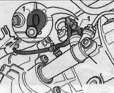
Vehicles with system «start-stop»: Disconnect electrical connector for gearbox neutral position sensor -G701 - -1 - and free cable.
All
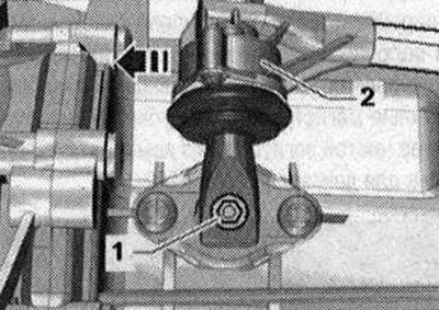
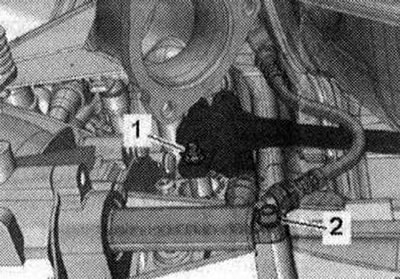
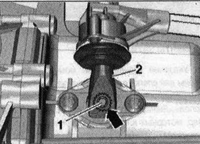
Unscrew the screw -2- and remove the clutch slave cylinder from the gearbox, removing the tube from the bracket. Tie the slave cylinder to the side of the engine. Risk of damage to the clutch slave cylinder. After removing the clutch slave cylinder, do not press the clutch pedal. Unscrew nut-1-.
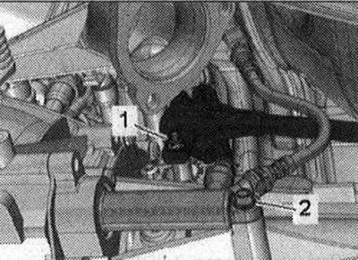
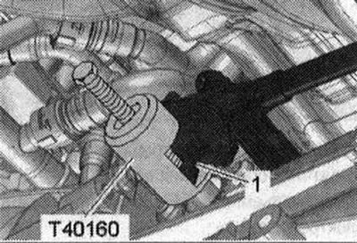
Risk of damage to the shift shaft in the gearbox. Do not press the shift shaft -1- with a pry bar or knock it down with a hammer. Install the puller -T40160- and remove the gearbox lever-1-.
Install a device for filling and pumping out oil under the disconnection point.
Unscrew bolts -arrows-, disconnect hydraulic line -1 - from steering gear and place to one side. To prevent the penetration of dirt, seal the disconnected lines and pipes on the intercooler with a clean plug from the engine plug set -VAS 6122-.
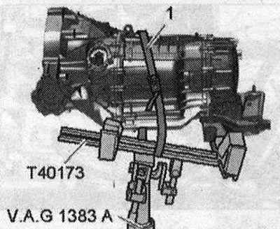
Remove starter bolt -1-. Disconnect the starter from the gearbox and leave it in its installation position. There is no need to disconnect the starter cables. Unscrew the remaining bolts -7 - 10- connecting the engine to the gearbox. Place the tilting mechanism with mounting bracket -T40173- under the gearbox and secure it with a harness -1-, as shown in the figure. When fixing the harness, make sure that the electric the gearbox wires were not pinched.
Unscrew the bolts -arrows- for the tunnel cross member. Press the gearbox away from the engine and carefully lower it using the tilt lever. When lowering, check that the cable is not pinched on the top side of the gearbox. When lowering, make sure the drive shafts move freely.
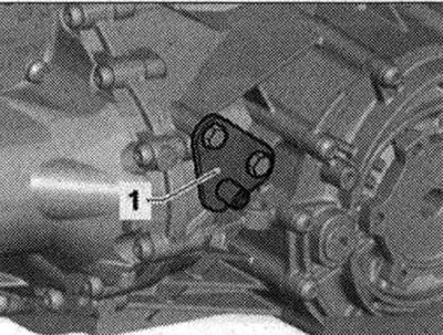
When replacing a removed gearbox, the following parts must be replaced with the new gearbox. Bracket -1- for exhaust system support strip. Tunnel cross member with gearbox cushion and gearbox support.
If necessary, remove the clutch module.
Installation
Note: The bolts that are tightened at the tightening angle must be replaced. Aluminum bolts for attaching the engine to the manual transmission can be used 2 times. Replace self-locking nuts and bolts and seals. rings, gaskets and seals. cuffs Hose fittings, air pipes and hoses must be cleaned of oil and grease before installation. To secure all hose connections, use clamps of the appropriate series. To ensure reliable fastening of the air charging hoses to the fittings, the threaded connections of already used clamps should be treated with a rust remover. During installation, all cable ties should be placed in the same places.
Tightening torques when installing the gearbox
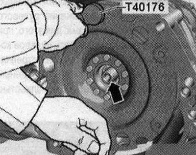
Place the gearbox on the gearbox bracket -T40173- and secure it with a harness -1 -, as shown in the figure. Check the input shaft where it is installed in the flywheel disc -arrow- for signs of running-in. If necessary, replace the flywheel disc needle bearing.
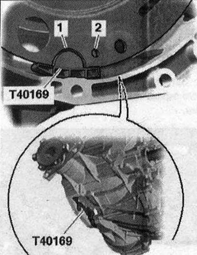
If necessary, install the clutch module. Before connecting the engine and gearbox, carry out the following preparatory steps. Insert mounting tool -T40169- into the gearbox housing from below and install the clutch module as shown in the illustration. The mounting device -T40169- must fit into the semicircular groove -1- and additionally into the inspection hole -2-. In order to find the inspection hole, you need to rotate the clutch module. Insert the bolts of the mounting device into the hole on the gearbox housing.
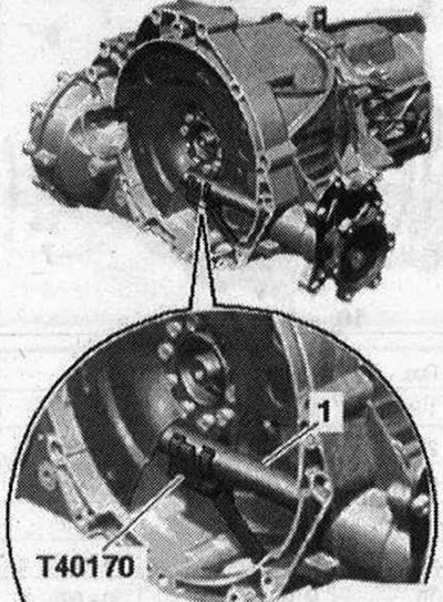
Place the transport protection -T40170- from below under the gearbox housing and attach it to the flange shaft -1-.
Check the presence of centering sleeves -A- for the engine and gearbox in the cylinder block, insert the sleeves if necessary. Pos. -1...10- do not take into account. Raise the gearbox so that the clutch slave cylinder can be installed. Tighten bolt -2-.
If necessary, check the possibility of reuse and mark the aluminum bolts -2...10- connecting the engine and gearbox. Place the engine on the gearbox and tighten the bolts -7...10- of the engine/gearbox connection. Install the starter and screw in the bolt -1- from the engine side by hand.
Attach bracket -B- with plug connector -C- for exhaust temperature sensor 4 -G648- to the gearbox. Secure email wire -A- to gearbox -arrows-.
Install gearbox lever -2- as follows. Gear shift lever -2 - can be installed on the shift shaft -1 - only in one position (recess in ring gear -arrow-). Tighten the bolt -2- of the gearbox lever.
Tighten the shift fork rod -1-. Tighten connecting rod -3-. Connect connector -2 of gear detection sensor -F208-. Remove harness -T10038-.
Continue lifting the gearbox and tighten the bolts -arrows- of the tunnel cross member. Remove the tilting mechanism with mounting bracket -T40173- from under the gearbox.
Remove the stretch. Unscrew upper starter bolt -2- with spacer between starter and gearbox -arrow-.
Tighten the remaining bolts -1...6- of the engine/gearbox connection.
Vehicles with start-stop system: Connect connector for gearbox neutral position sensor -G701--1-.
All
Screw the universal joint to the steering gear.
Screw the drive shafts on the right and left to the gearbox flange shafts.
Install the drive shaft heat shield.
Sequence of tightening bolts clutch module to driven disc
Remove transport securing device -T40170- and mounting device -T40169-. Engage 6th gear, to do this, remove the shift shaft -1- and shift the gearbox lever -2- forward in the -direction of the arrow-.
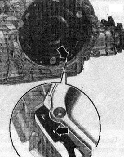
The next stage of work is absolutely necessary to ensure uniform contact with the driven disk without distortion. Rotate both front wheels in the same direction until the clutch module makes 1 full revolution. The inspection hole -arrow- should again be visible in the recess of the gearbox housing.
I
Tighten the clutch module bolts on the driven plate as follows: Use only new bolts. Tighten the bolts with a 16 mm ring spanner -VAG 1332/14-. Screw in the first bolt -arrow- all the way (2 Nm).
Rotate the clutch module through the front wheels 120°in the direction of engine rotation and tighten the second bolt by hand (2 Nm). Rotate the clutch module again 120°in the direction of engine rotation. Screw in and tighten the third bolt. Now tighten the 2 remaining bolts. Installation is in reverse order, observing the following. Install the particulate filter and exhaust pipe. Install the air housing. filter. Install the power steering lines. Check the oil level in the manual transmission. Install the subframe cross. Install soundproofing screens. Install a stretcher. Pay attention to the battery installation work.
Tightening torques (Nm)
Note: The tightening torques given apply to lightly lubricated, phosphated or oxidized nuts and bolts. It is allowed to use additional lubricants, for example, motor or transmission oils, with the exception of graphite-containing lubricants. Do not use degreased parts. The tightening torque tolerance is±15%.
P. I
| Bolts and nuts | |
| M6 | 9 |
| M7 | 15 |
| M8 | 20 |
| M10 | 40 |
| M12 | 65 |
Heat shield for drive shaft - tightening torque
Tighten the bolts -arrows- for the heat shield of the drive shaft to 23 Nm.
Mounting the 2.0-litre TDI engine to the manual gearbox
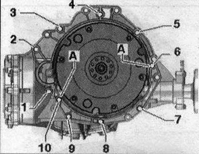
| POS. | Bolt | Nm |
| 1 (1) | M10x50 (2) | 65 |
| 2 (3) | М12Х100 (4) | 30 + 90° |
| 3 (5), 6 | M12x75 (4) | 30 + 90° |
| 4,5 (5) | M12x120 (4) | 30 + 90° |
| 7...9 | M1 0x75 (4) | 15 + 90° |
| 10 | M12x50 (4) | 30 + 90° |
| A | Centering sleeves | |
- (1) Additionally secures the starter.
- (2) The steel bolt is not replaceable.
- (3) Additionally secures the starter; with additional spacer between the starter and gearbox.
- (4) Check that aluminum bolts can be reused and replace if necessary.
- (5) Additionally, the electrical wire bracket is attached.
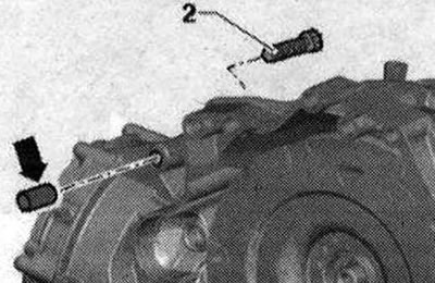
Aluminum bolts -2...10- may not be used more than 2 times. Therefore, after the first use, mark such bolts with two notches using a cutter "X" -arrow-.
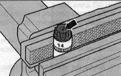
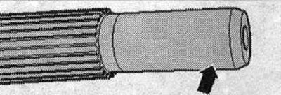
To avoid damaging the bolts when notching, do not secure them in a vice. Insert the bolt, as shown in the figure, into the 14 socket head using 1/2" -drive, which can then be secured in a vice. Tagged "X" Do not reuse bolts. The steel bolt -1- can be used repeatedly.
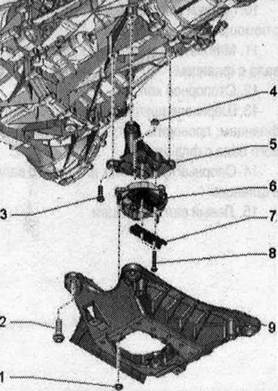
Tunnel cross member, gearbox mount and gearbox support 1/4. Nut: 20 Nm; 2. Bolt: 70 Nm; 3. Bolt: 40 Nm; 5. Gearbox support; 6. Gearbox cushion; 7. Lower stop: for gearbox cushion; 8. Bolt: 20 Nm + 90°; replace; 9. Tunnel cross member
Visitor comments