Repair Chevrolet Repair Toyota Repair Honda Repair AvtoVAZ Repair Mercedes-Benz Repair BMW Repair Opel
Home  |  Contacts  |  Sitemap  |    
English Русский
Български
Беларускі
Український
Српски
Hrvatski
Română
Polski
Slovenský
Magyar
AudiManual.ru


  • AUDI 80
  • AUDI 100
  • AUDI A3
  • AUDI A4
  • AUDI A6
  • AUDI A8
  • AUDI Q
  • OTHER
  • ARTICLES
Q7 Typ 4L (2005-2015, diesel) Q5 Type 8R (2008-2017)

Gear shift mechanism (Audi Q5-8R)

  • Home
  • Audi Q
  • Q5 Type 8R (2008-2017)
  • Transmission
  • Manual gearbox 0B1
  • Gear shift mechanism
            0
Table of contents: Removal the ball head with the cuff… ↓ Installation ↓ Removal sound insulation ↓ Installation ↓ Mounting position of the push rod ↓
Gear shift mechanism «Arrow A». Switching stroke; «Arrow B». Movement of choice; 1. Connecting rod;…

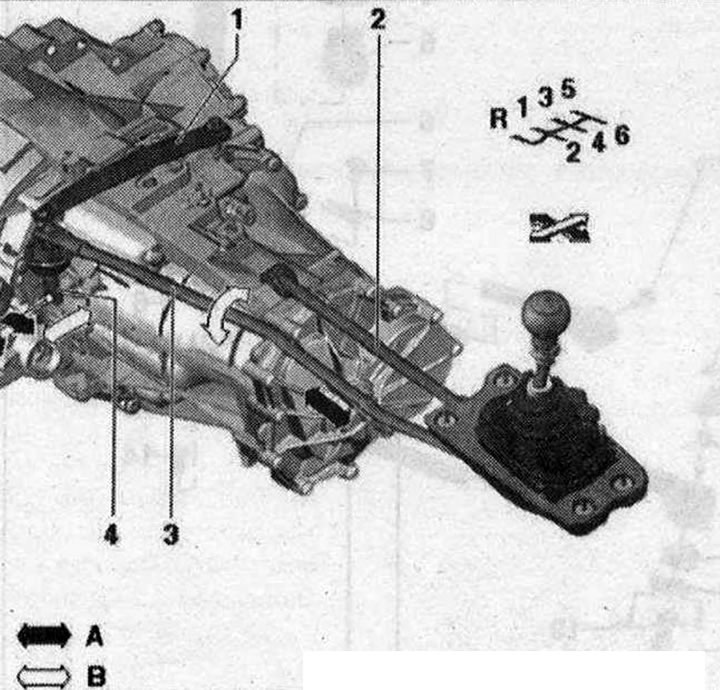
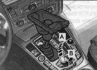
Gear shift mechanism "Arrow A". Switching stroke; "Arrow B". Movement of choice; 1. Connecting rod; 2. Push rod; 3. Shift rod; 4. Gear shift lever


Handle with gearshift lever cover 1. Shift button with gearshift lever sleeve; 2. Clamp: secures…

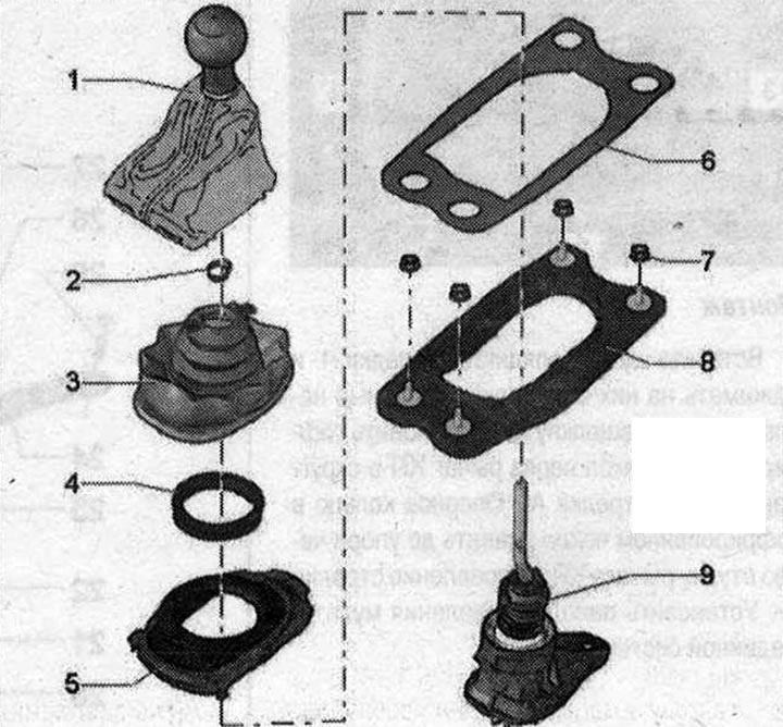
Handle with gearshift lever cover 1. Shift button with gearshift lever sleeve; 2. Clamp: secures the shift knob to the gear shift lever; secure with VAG 1275- hose clamp clamp; 3. Corrugated cover (dust cover): supplied only assembled with support ring; remove and install together with sound insulation; 4. Support ring: supplied only assembled with corrugated casing; 5. Soundproofing; 6. Gasket; 7. Nut: 8 Nm; 8. Support mount: for shift lever bushing; 9. Gear shift lever with lever bushings


Removal the ball head with the cuff of the gearbox lever


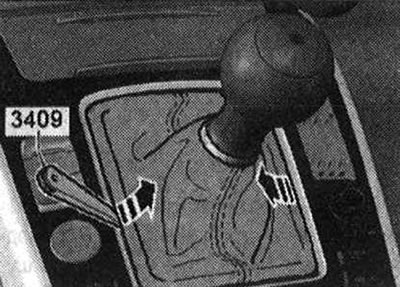
The gearshift lever handle is removed together with the gearshift lever sleeve. Lift the gearshift lever sleeve using wedge "3409" "arrows" and pull it upwards.

The gearshift lever handle is removed together with the gearshift lever sleeve. Lift the gearshift…


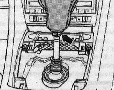
Turn the cuff upwards through the shift handle. Open the "arrow" clamp and remove the shift handle together with the cuff of the gearbox lever.

Turn the cuff upwards through the shift handle. Open the «arrow» clamp and remove the shift handle…


Installation


Installation is in reverse order. Secure the "arrow" clamp with clamp pliers "V.A.G 1275".

Removal sound insulation


Turn off the ignition. Remove the gearshift knob with the gearshift lever sleeve. Remove the E380 multimedia system control panel.

Turn off the ignition. Remove the gearshift knob with the gearshift lever sleeve. Remove the E380…


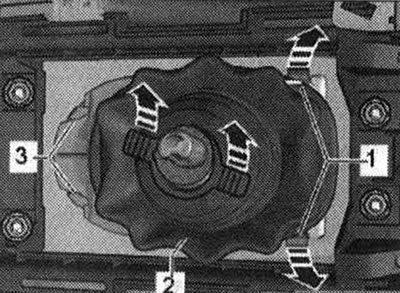
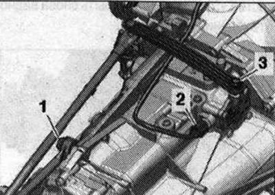
Unlock the locking pads "1" in the "direction of the arrow". At the same time, lift the rear noise insulation. Remove the noise insulation screen from the fasteners "3". Remove the corrugated cover "2" from the gearshift lever "in the direction of the arrow".


Unlock the locking pads «1» in the «direction of the arrow». At the same time, lift the rear noise…


Installation


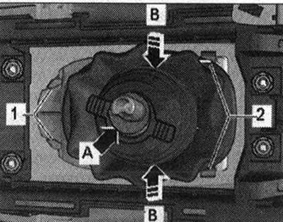
Insert the sound insulation into the pads "1" and press them down until the locking pads "2" snap into place. Install the corrugated cover through the gearbox lever into the rounded groove "arrow A". Press the support ring in the corrugated cover all the way through the gearbox lever bushing - direction of arrow B-. Install the control panel of the multimedia system "E380".

Insert the sound insulation into the pads «1» and press them down until the locking pads «2» snap…


Install the shift knob with the gearshift lever sleeve.

Gear shift mechanism 1. Retaining ring: remove the ball to remove; 2. Spacer sleeve; 3. Pressure…

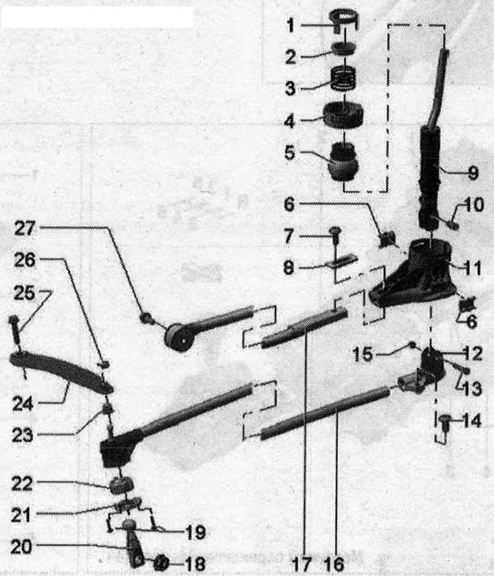
Gear shift mechanism 1. Retaining ring: remove the ball to remove; 2. Spacer sleeve; 3. Pressure spring; 4. Ball guide: Do not lubricate; 5. Ball: Do not lubricate; 6. Sound insulation: shift lever bushings; do not lubricate; 7/14. Bolt: 23 Nm; 8. Clamping plate: do not lubricate; 9. Selector: bend facing backwards; if necessary, lubricate the immersion pressure guide and the shift lever stops; 10. Remote tube; 11. Shift lever bearing: do not lubricate; 12. Hinge element: between the rod and the shift lever; lubricate if necessary; 13. Bolt: for hinge; 15. Nut: 10 Nm; 16. Shift rod; 17. Push rod: with bolt and washer; 18. Nut: 20 Nm; replace; 19. Bolt: 4 Nm; 20. Gear shift lever: install so that the splines on the shift shaft match; lubricate if necessary; 21. Sealing cuff; 22. Ball joint: lubricate if necessary; 23. Support bushing: to remove, remove the protective bracket; 24. Connecting rod: to remove, remove the protective bracket; 25/27. Bolt: 20 Nm; 26. Locking clamp


Mounting position of the push rod


Mounting position of the push rod


Push rod "1" is screwed to the left side of the gearbox cover.
The article was checked by auto expert Timur Bazhenov
This article is available at russian, bulgarian, belarusian, ukrainian, serbian, croatian, romanian, polish, slovak, hungarian

Share information:
Previous articles
Audi Q Q5 Type 8R: Manual gearbox 0B1
Next articles

Clutch module
Replacing the clutch slave cylinder
Removal the clutch master cylinder
Clutch engagement noises
Removal the gear shift mechanism
Adjusting the gear shift mechanism
Checking the gearshift lever adjustment
Gearbox removal — vehicles with 4-cylinder diesel engine


Similar articles on other Audi car models:
Gear shift control mechanism Audi 80 B2 (1979-1986)
Gear shift control mechanism parts Audi 100 C3 (1982-1990, petrol)
Gear shift drive Audi A3 Type 8L (1996-2003)
Adjusting the gear shift mechanism Audi A4 B6 (2000-2006, petrol)
Adjusting the gear shift mechanism Audi A6 C5 (1997-2004)
Valve mechanism Audi A8 D2 (1994-2002)
Mounting position of the gear shift mechanism Audi A2 (1999-2005)
Link to this page in different formats


Visitor comments

No comments yet


How much will 50 + 33 =


Q7 4L(2005-2015, diesel) 
  • General information
  • Operating instructions
  • Maintenance
  • Power unit
  • Diesels 3.0 l (BUG, BUN, CAS)
  • Diesels 3.0 l (CATA, CCMA)
  • Diesels 3.0 l (CJGA/CJGC)
  • Diesels 4.2 l (BTR, CCFA/CCFC)
  • Cooling system
  • Fuel and exhaust system
  • Engine management system
  • Starting and charging
  • Transmission
  • Automatic gearbox
  • Drive shafts
  • Chassis
  • Brake system
  • Front suspension
  • Rear suspension
  • Steering system
  • Body
  • Air conditioner
  • Exterior
  • Interior
  • Electrical equipment
  • Equipment and devices
  • Electrical circuits
 
Q5 8R(2008-2017) 
  • General information
  • User manual
  • Power unit
  • Petrol engine 2.0 l
  • Petrol engine 3.2 l
  • Fuel system (petrol)
  • Diesel 2.0 liter (CA)
  • Diesel 2.0 liter (CG/CJ/CM)
  • Diesel engine 3.0 l
  • Fuel system (diesel)
  • Transmission
  • Manual gearbox 0B1
  • Manual gearbox 0B2
  • Automatic gearbox 0B5
  • Automatic gearbox 0B6
  • Chassis
  • Front suspension
  • Rear suspension
  • Brake system
  • Steering
  • Body
  • Exterior
  • Interior
  • Doors, locks and windows
  • Safety system
  • Ventilation and heating
  • Electrical equipment
  • Power devices
  • Equipment and devices
  • Lighting and alarm
  • Audio system
  • Electrical circuits
 
AudiManual.ru © 2017-2026 · Mobile version · Feedback · Sitemap: EN BG BY UA RS HR RO PL SK HU · Site search · News and articles
80 B2 · 80 B3 petrol · 80 B3 · 80 B4 · 100 C3 diesel · 100 C3 petrol · 100 C3 · 100 C4 petrol · 100 C4 · A3 Type 8L · A4 B5 petrol · A4 B5 · A4 B6 petrol · A4 B6 · A4 B7 · A4 B8 · A6 C4 · A6 C5 · A6 C5 Allroad · A8 D2 · Q5 Type 8R · Q7 Typ 4L · Audi A2 ·
This site uses cookies 🍪. Click the button to accept this fact.