
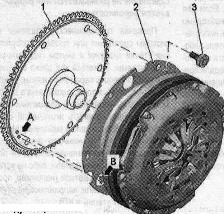
Clutch module A. Locking pin: not available on all vehicles; when connecting the clutch module "2" to the driven disk "1" the locking pin "A" (if available) should fit into hole "B"; B. Fixing hole: when connecting the clutch module "2" to the driven disk "1", the fixing pin "A" (if available) should fit into hole "B"; 1. Driven disk: in 4-cylinder engines - 3 holes with threaded bushings; in 6-cylinder engines - 6 holes with threaded bushings; with needle bearing; 2. Clutch module: with plate; components: Dual mass flywheel, clutch disc and clutch basket; 3. Bolt: 60 Nm; for mounting a dual mass flywheel on a driven disk; 3 pcs. in a car with a 4-cylinder engine; 6 pcs. in a car with a 6-cylinder engine; always subject to replacement; observe the tightening sequence
Caution! Problem with clutch operation due to incorrect installation. If the retaining pins of the driven disk "A" do not enter the holes of the clutch module "B", this can lead to serious problems with the clutch operation.
Bolt tightening sequence - clutch module to driven disc
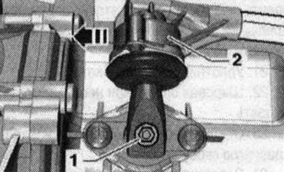
Tighten the bolts with a 16 mm ring spanner - VAG 1332/14 ". 6" gear is engaged, to do this, remove the shift shaft "1" and shift the gearbox lever "2" forward in the "direction of the arrow".
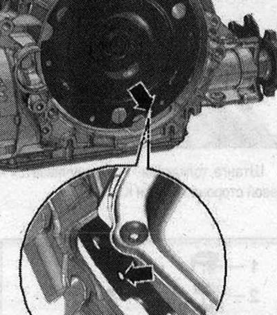
The next stage of work is absolutely necessary to ensure uniform contact with the driven disk without skewing. Rotate both front wheels in one direction so that the clutch module makes 1 full revolution. The control hole "arrow" should be visible again in the recess of the gearbox housing.
Vehicles with 4-cylinder engine: Screw in the first bolt "arrow" all the way (2 Nm). Turn the clutch module by 120° in the direction of engine rotation using the front wheels and tighten the second bolt by hand (2 Nm). Turn the clutch module again by 120° in the direction of engine rotation. Screw in and tighten the third bolt. Now tighten the 2 remaining bolts to the specified tightening torque.
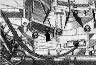
Cars with 6-cylinder engine: Screw in the first bolt "arrow" (2 Nm) all the way. Turn the clutch module by both front wheels 180° in the direction of engine rotation. Now screw in the second bolt and tighten to the specified torque. Now screw in the remaining bolts one by one and tighten immediately (even a bolt that has just been screwed in) moment.
The original article is available on the online resource: AUDImanual.ru