
Also check that the shift rods move freely and are in good condition.
Adjustment
Place the gear shift lever in neutral and apply the handbrake.
Remove the gear shift boot from the center console.
Unscrew the handle from the gear shift lever and remove it together with the boot.
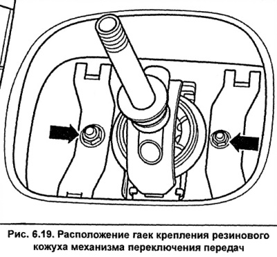
Unscrew the nuts and remove the rubber cover of the gearshift housing (see fig. 6.19).
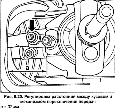
Measure the distance a (Fig. 6.20) between the body and the gearshift mechanism, which should be 37 mm. If necessary, adjust it as follows. Loosen the bolt (arrow, Fig. 6.20) fastening the gear shift fork shaft. By moving the shaft, ensure that the dimension a is 37 mm, and tighten the fastening bolt to a torque of 25 Nm.
Loosen nuts A and B (Fig. 6.21) securing the ball joint housing. Install the ball joint housing horizontally relative to the direction of travel.
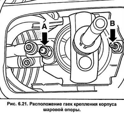
Tighten nuts A and B (Fig. 6.21) securing the ball joint housing to a torque of 25 Nm.
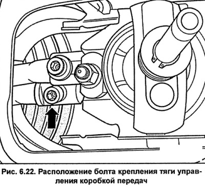
Loosen the transmission control rod mounting bolt (see fig. 6.22).
Install the gearshift lever by tilting it longitudinally slightly backwards. For cars with a V6 diesel engine, the lever should be tilted backwards by 7°.
Position the gearshift lever so that the projections of the ball stop are at the same distance from the housing a (Fig. 6.23). On vehicles with a V6 diesel engine, the gearshift lever can be deflected to the right by a maximum of 3° when viewed from the rear of the vehicle.
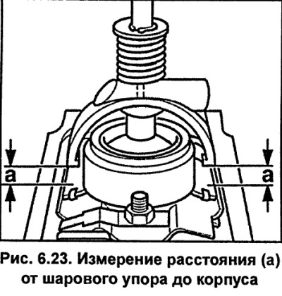
Without moving the gearshift lever, tighten the gearshift rod mounting bolt to 25 Nm. Check that the position of the gearshift lever has not changed.
Check the correct installation of the gear shift lever. When free, the gear shift lever should be in the third-fourth gear position.
Check the shifting of all gears. Pay attention to the action of the reverse gear lock. Note: do not shift to reverse gear and fifth gear, the locks of these positions should be checked in the workshop.
All models except for cars with V6 diesel engines. Additional adjustment can be made as follows. Loosen nuts A and B (Fig. 6.21) securing the ball housing. Move the gearshift lever all the way to the right and the ball housing to the left of the lever and in this position re-tighten the fastening nuts to a torque of 25 Nm.
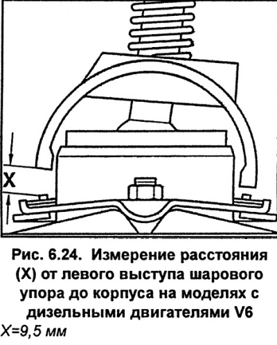
V6 diesel models: To make further adjustments, loosen the transmission control rod mounting bolt (see fig. 6.22). Position the gearshift lever so that the left projection of the ball stop is 9.5 mm from the housing (see fig. 6.24). Without moving the gearshift lever, tighten the gearshift rod mounting bolt to 25 Nm. Check that the position of the gearshift lever has not changed.
Install and screw in the gearshift rubber boot.
Screw the knob onto the gear shift lever.
Attach the gear shift boot to the center console.
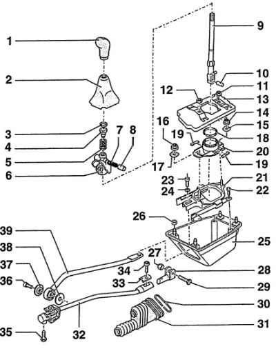
Fig. 6.25. Gear selection mechanism
1 - handle,
2 - case,
3 - retaining ring,
4 - spacer sleeve,
5 - spring,
6 - ball stop,
Spring 7 and sleeve 8 are installed in the ball stop and are secured to the gear shift lever in such a way that they are located on the right in the direction of vehicle movement.
7 - spring,
8 - bushing,
The spherical side of the bushing should be on the gear shift lever side.
9 - gear shift lever,
The gear shift lever can only be set in one position.
10 - intermediate sleeve,
11 - nut, 10 Nm,
12 - nut, 10 Nm,
13 - facing coating,
14 - nut, 25 Nm,
15 - connecting link,
16 - nut, 25 Nm,
17 - connecting link,
18 - retaining ring,
When installing, a new retaining ring must be used. The convex side of the ring must face the housing.
19 - buffer,
20 - ball housing,
21 - rear shaft of gear shift fork,
22 - bolt, 10 Nm,
23 - bolt, 25 Nm,
24 - washer,
25 - body,
26 - nut, 10 Nm,
27 - self-locking nut, 10 Nm,
A new nut must be used during installation.
28 - shift fork,
29 - bolt,
30 - elastic clamping ring,
31 - protective cover,
32 - control rod,
33 - clamp,
34 - bolt, 25 Nm,
35 - self-locking bolt, 20 Nm,
A new bolt must be used during installation.
36 - bolt, 40 Nm,
37 - washer,
When installing, the convex side of the washer should face the control lever.
38 - washer,
39 - gear shift rod.
Note
- On models with V6 diesel engines, the design of the rod attachment to the gearbox differs from that shown in the figure.
- If it is necessary to completely remove the gearshift mechanism, the exhaust system must first be removed.
(The original article is available on the online resource «AudiManual»)