
Caution. The operations for removing and installing a special automatic transmission are similar to those for removing and installing a manual transmission and are given at the beginning of the chapter. In the following, only the operations related to the special automatic transmission in combination with a 4-cylinder engine are given.
Support the weight of the engine with a lifting device using the eyes attached to the cylinder head.
Mark connection points C and D (Fig. 6.14) and disconnect electrical connectors A to D from the gearbox.
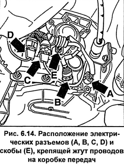
Unscrew the bracket E (Fig. 6.14) securing the wiring harness to the gearbox.
Unscrew the oil cooler pipes from the engine and gearbox.
Caution: To prevent dirt from getting into the pipes, wrap their ends with adhesive tape or close them with suitable plugs.
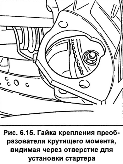
Unscrew the three torque converter mounting nuts (hydraulic transformer) to the drive disk. Using a wrench, turn the engine crankshaft clockwise by the crankshaft pulley mounting bolt to a position where one of the torque converter mounting nuts is accessible through the starter hole. Using a screwdriver or crowbar, secure the drive plate from turning by the flywheel ring gear teeth and unscrew the torque converter mounting nut. Turn the engine crankshaft and unscrew the remaining two nuts in the same way (see fig. 6.15).
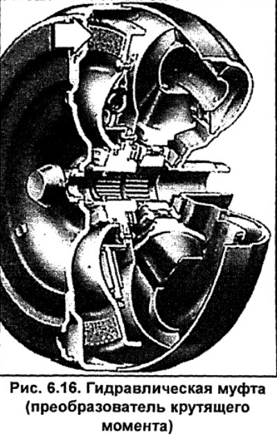
Note: The torque converter is located between the engine and the gearbox and is a hydraulic clutch (see fig. 6.16). A hydrodynamic coupling is used to transmit engine torque by means of a fluid circulating in their working cavity. This device compensates for the difference in engine and transmission speeds, and performs the transition from a stationary state to movement. A hydrodynamic coupling also allows increasing torque. The pump wheel of a hydraulic coupling converts mechanical energy received from the engine into hydraulic energy of the working fluid (ATF), and the reconversion back into mechanical energy occurs on the blades of the turbine wheel. The advantages of a hydraulic coupling include: stepless change in torque and speed, damping of torsional vibrations, absorption of peak moments and power transmission without noticeable wear.
Set the selector lever to position "P" and, pulling up, disconnect the gearbox control cable from the shaft.
Remove the bolt securing the gearshift cable housing and remove the cable.
Move the transmission away from the engine while supporting the torque converter.
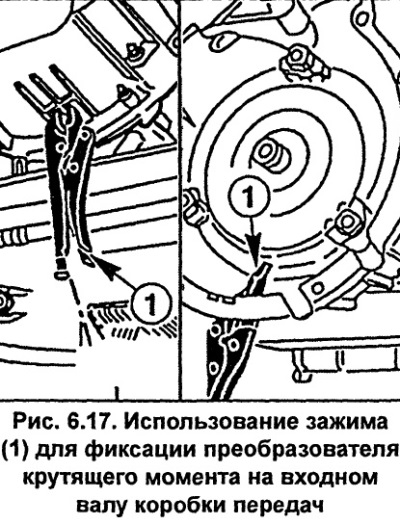
Move the torque converter along the input shaft to the transmission housing and use pliers to secure it in this position (see fig. 6.17).
Carefully lower the transmission and remove it from under the vehicle.
Installation
Remove the pliers holding the torque converter to the transmission input shaft.
Using three nuts, screw the torque converter to the drive plate and tighten the nuts to a torque of 85 Nm.
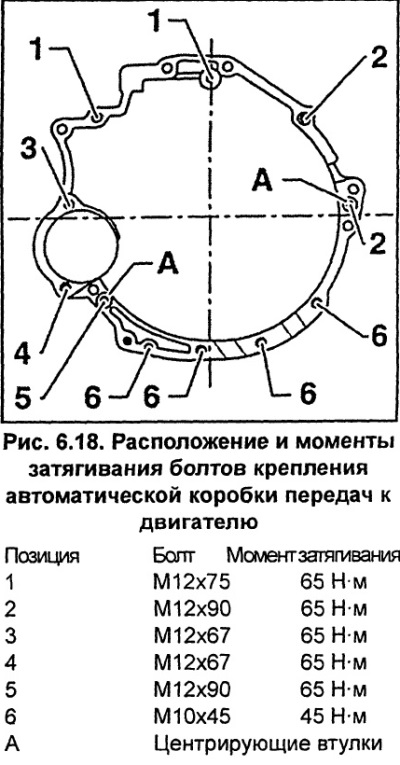
Screw in the gearbox mounting bolts to the engine and tighten them to the required torque (see fig. 6.18).
Check that the selector lever is in the "P" position and connect the transmission control cable to the transmission shaft.
Secure and, if necessary, adjust the transmission control cable.
Check the gearbox oil level and top it up if necessary.
(The text is based on materials from the website: AudiManual)