
Table of contents: Models with 1.8-I/150 hp engine. ↓ Models with 4-cylinder engines ↓ Models with V6 petrol engines ↓ Models with 4-cylinder engines ↓ Models with V6 petrol engines ↓ Models with 1.8-1/150 hp engine. ↓
Before removing the gearbox, the vehicle must be raised and secured in this position. A stationary jack must also be used to support and lower the gearbox.
To remove and install manual transmissions, perform the following operations. Instructions for automatic transmissions are provided at the end of the chapter.
Removal
Disconnect the ground cable from the battery.
Attention
- When disconnecting the wires from the battery terminals, the memory units of the control units erase the data on the recorded faults, so before disconnecting the wires, you must contact a workshop to recall the faults recorded in the memory. After connecting the wires to the battery terminals, it is necessary to activate and reprogram the electric windows, as well as the position of the rear-view mirrors and seats.
- If the car has a radio receiver with a code, then before disconnecting the wires from the terminals from the battery, check that there is a code to reactivate the receiver. Otherwise, the radio receiver can only be put into operation at a specialized station.
Unscrew and remove the expansion tank of the cooling system from the bracket and, without disconnecting the hoses from it, move it to the side.
Loosen the clamps and remove the air duct located between the air filter and the engine.
Models with 1.8-I/150 hp engine.
Remove the air filter.
Mark the position of the right front wheel in relation to the hub with paint. This is necessary to reinstall the wheel in its original position, as a result of which its balance is maintained. With the car standing on its wheels, loosen the bolts securing the right front wheel, then lift the car, unscrew the bolts and remove the right front wheel.
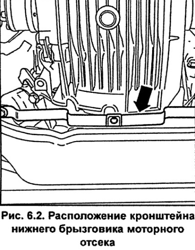
Remove the lower engine compartment splash shield.
Unscrew the bolts and remove the lower engine compartment splash guard bracket (see fig. 6.2).
Unscrew and remove the exhaust pipe and catalytic converter.
Unscrew and remove the engine crankshaft speed sensor located on the left side of the gearbox.
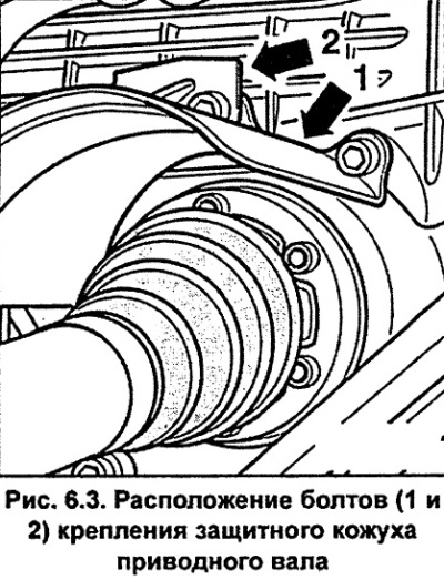
If present, unscrew the bolts and remove the protective covers of the right and left drive shafts (see fig. 6.3).
Unbolt and disconnect the inner drive shaft joints from the transmission drive flanges. Using soft wire, tie the inner ends of the drive shafts to the body. It is not recommended to lower the drive shafts freely, as this can cause damage to the outer constant velocity joints (CV joints)
Remove the starter.
Note: There is no need to disconnect the wires from the starter if it unscrews and is attached to the body with wire.
Unscrew the fastening bolt A (Fig. 6.4) of the gearbox control rod and remove the rod from the gearbox.
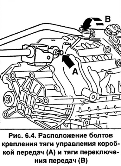
Unscrew bolt B (Fig. 6.4) with an internal hexagon and disconnect the gear shift rod from the gearbox.
Disconnect the ground wire from the transmission.
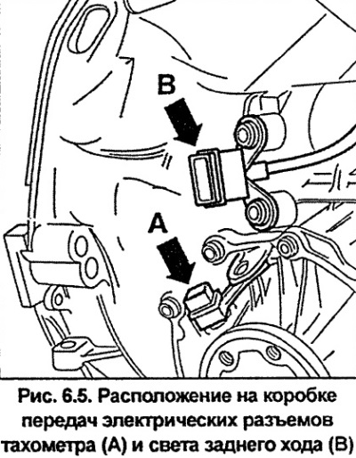
Disconnect the electrical connectors for the tachometer A and the reversing light B from the gearbox (Fig. 6.5).
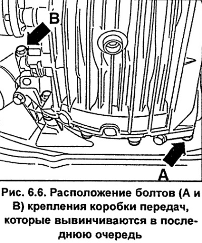
Unscrew the bolts securing the gearbox to the engine, leaving bolts A and B in place (Fig. 6.6).
Install a special lift with a 3282 socket and an adjustment plate 3282/10 for a 012/01A gearbox and installation elements under the gearbox. Screw the gearbox to the socket and the adjustment plate (see fig. 6.7). Raise the VAG1383A lift so that the weight of the gearbox is supported by the lift.
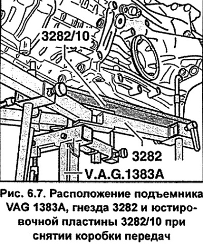
Attention. If there are no special devices for removing the gearbox, support the gearbox with a jack through a wide wooden block.
Models with 4-cylinder engines
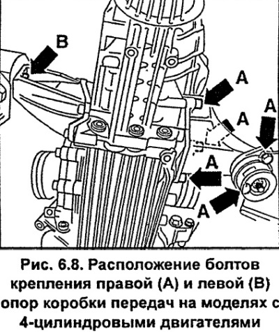
Unscrew bolts A (Fig. 6.8) securing the right rubber-metal support of the gearbox. Unscrew bolt B (Fig. 6.8) securing the bracket from the left support of the gearbox.
Models with V6 petrol engines
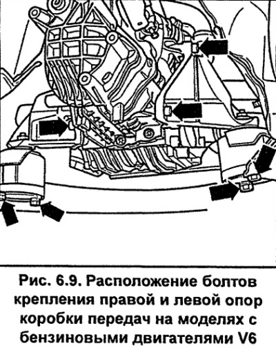
Unscrew the bolts securing the right and left rubber-metal mounts of the gearbox (see fig. 6.9).
Unscrew the remaining two bolts A and B (Fig. 6.6) securing the gearbox to the engine.
Press the gearbox away from the engine, remove it from the centering bushings and lower it by 15 cm until the clutch slave cylinder is accessible.
Unscrew the clutch slave cylinder and tie it to the body with soft wire (see fig. 6.10).
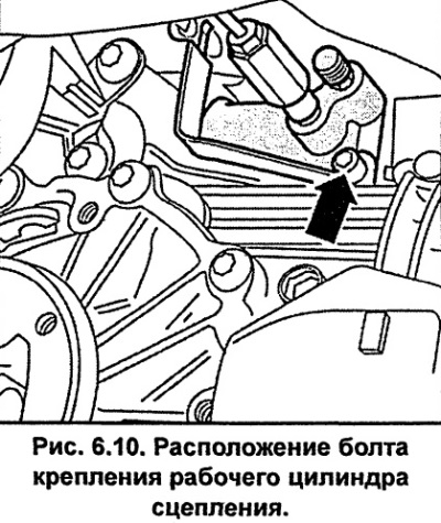
Caution: The hydraulic hose remains connected to the clutch slave cylinder, otherwise bleeding will be required after installation. Do not press the clutch pedal while the clutch slave cylinder is removed.
Carefully lower the transmission and remove it from under the vehicle.
Installation
Please note. Gearbox housings can be made of either aluminum or magnesium alloy. Depending on the material of the gearbox housing, all parts connected to the gearbox, including bolts and screws, must be coordinated. If gearbox parts with an aluminum alloy housing are installed in a magnesium alloy housing, the housing will be subject to corrosion. This also applies to the gearbox mounting bolts on the engine, which must be coated with a special protective layer for magnesium alloy housings. If the gearbox housing is made of magnesium alloy, there is an inscription Mg AI9 Zn 1 near the oil filler plug.
Before installing the gearbox, check the condition of the clutch components.
Clean the splined portion of the gearbox input shaft and lubricate with a thin layer of MoS2 or AUDI 000 100 grease.
Caution. The lubricant layer must be thin and the clutch drive disc must move easily along the gearbox input shaft. Wipe off excess lubricant, as it will be thrown onto the clutch working surfaces during clutch operation, which may impair its operation.
Apply a thin layer of grease to the pushrod head that mates with the clutch release fork.
Check that the gearbox alignment bushings are installed in the engine block and install them if necessary.
Check the position of the engine intermediate shield.
Lift the gearbox and move it toward the engine, with the gearbox input shaft aligning with the clutch disc. You may need to turn the engine crankshaft slightly to align the gearbox input shaft splines with the clutch disc splines. When installing the gearbox, the input shaft should not hang on the clutch disc.
Install and secure the clutch slave cylinder to the pipe bracket. Press the gearbox to the engine, insert the bolts securing the gearbox to the engine and at this stage tighten the gearbox mounting bolts to 25 Nm.
Install the starter.
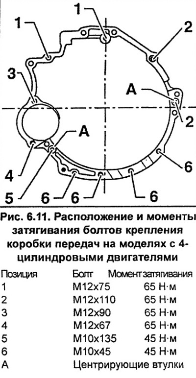
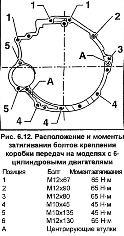
Tighten the gearbox to engine mounting bolts to the specified torque (see fig. 6.11, 6.12).
Connect the ground wire to the transmission.
Models with 4-cylinder engines
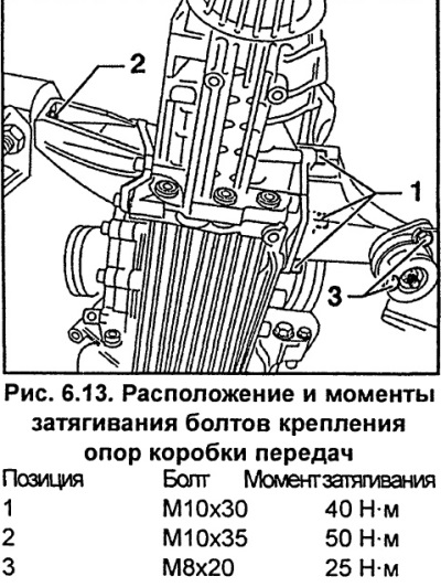
Screw in and tighten the gearbox support/assembly bracket mounting bolts in sequence 1,2,3 (Fig. 6.13).
Models with V6 petrol engines
Screw in and tighten the bolts securing the right and left rubber-metal mounts of the gearbox (see fig. 6.9). Tighten the bolts securing the supports to the gearbox to a torque of 40 Nm, and the bolts securing the supports to the brackets to a torque of 25 Nm.
Remove the transmission jack.
Connect and bolt the drive shafts to the gearbox.
Install the drive shaft protective covers and secure them with bolts, tightening them to a torque of 20 Nm.
Install and screw the control rod A (Fig. 6.4) to the gearbox with a torque of 20 Nm and the shift rod B with a torque of 40 Nm.
Connect the tachometer and reverse light electrical connectors to the gearbox.
Install the exhaust pipe.
Install and secure the expansion tank.
Models with 1.8-1/150 hp engine.
Install the air filter.
Install the air duct with the air flow meter and secure it with clamps.
Connect the ground wire to the battery. Repeat the steps to memorize the position of the seats, mirrors, etc., and also set the time on the clock and enter the code into the radio.
Check and, if necessary, top up the gearbox oil level.
Install the upper engine cover.
Install the lower engine splash shield.
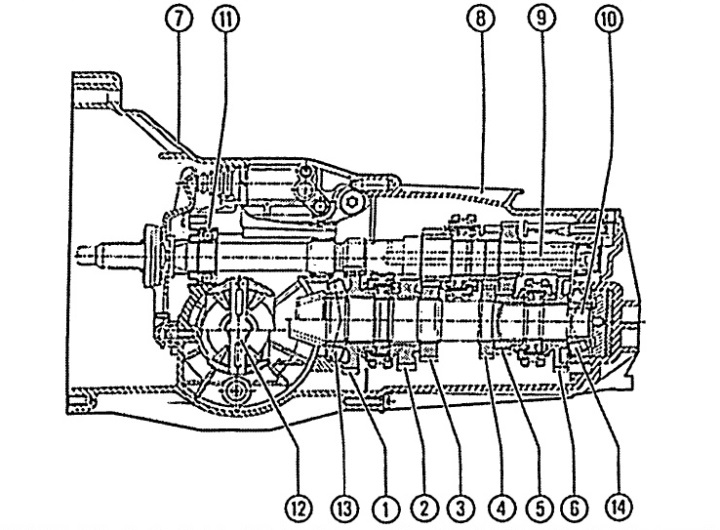
Fig. 6.1. Sectional view of a five-speed gearbox
1 - first gear pinion,
2 - second gear pinion,
3 - third gear pinion,
4 - fourth gear pinion,
5 - fifth gear pinion,
6 - reverse gear,
7 - gearbox housing,
8 - gearbox cover,
9 - input shaft,
10 - output shaft,
11 - ball bearing,
12 - differential,
13 and 14 - roller bearings.