Table of contents: Engine number ↓ Engine removal - cars with… ↓ Disconnecting the engine and gearbox… ↓
Engine number
The engine number will only be visible after removing the engine cover. compartment.
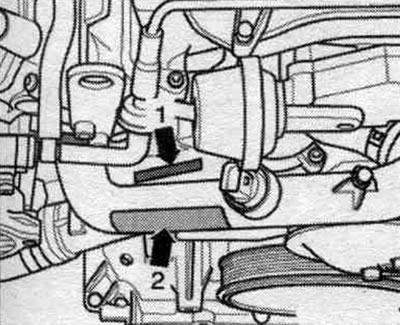
For more details, see the 3.0L engine.
Engine removal - cars with multitronic 0AW gearbox
Instructions: The engine with gearbox and subframe is removed downwards with the radiator frame installed. When reassembling, install all binders in the places where they were originally installed. Risk of injury from fuel under very high pressure. Before depressurizing the system. injection, it is necessary to release the fuel pressure to the residual pressure. Relieve fuel pressure in the high pressure sector. Bring the front wheels into a straight-ahead position. Follow the instructions when disconnecting the battery terminals.
Turn off the ignition. Disconnect ground wire "2" from the battery terminal. Drain the air conditioning circuit. Pump out the hydraulic oil from the power steering using a device for pumping oil from the reservoir.

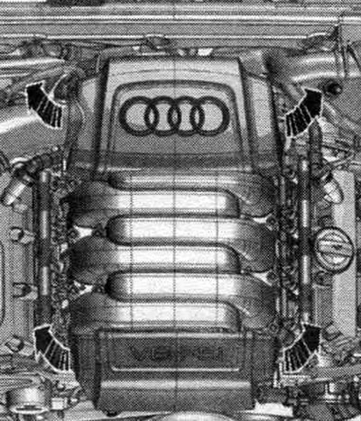
Remove the motor covers. "arrow" compartment. When the engine is warm, the cooling system is under excess pressure.
Open the expansion lid. tank.
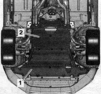
Remove the front wheels: right and left. Remove the front right and left fender liner. Remove noise insulation screens "1" and "2".
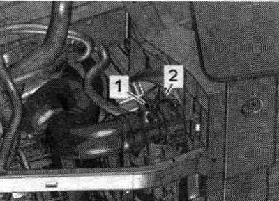
Place a service tray under the engine. Unscrew drain plug "1" and drain the coolant. Then remove the coolant hose from the radiator by loosening retaining clip "2.".
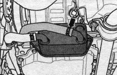
Remove the coolant hose "arrow" from the oil radiator and drain the residual coolant.
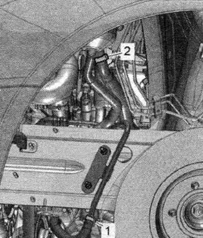
Place an oil suction device under the disconnection point. Disconnect the supply hose "2" and return hose "1" for the power steering hydraulic oil in the left front wheel arch and release. Close open lines and pipes with clean plugs from the VAS 6122 engine plug kit.
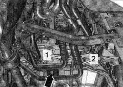
Place an oil suction device under the disconnection point. For correct assembly, mark the mounting. position ATF hydraulic lines "1" and "2" and disconnect the ATF hydraulic lines. Close the open lines and connections with clean plugs from the VAS 6122 engine plug kit. Ignore the "arrow.".
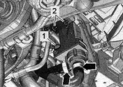
Vehicles with a "V50" coolant circulation pump: Disconnect plug "1". Place a service tray under the engine. Disconnect the coolant hose from the coolant circulation pump "V50" -arrow on the right-. "Pos. 2" and -left arrow- do not take into account.
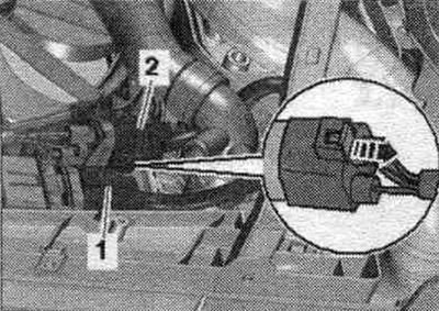
All
Disconnect the plug connectors "1" and, if present, "2" of the radiator fan. To do this, move the fuse back "arrow" and press the lock down. Release the wiring harness.
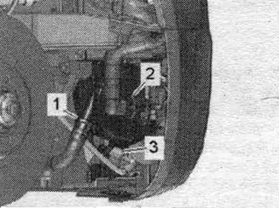
If present, disconnect plug connector "3" of the secondary air pump motor "V101" and release the electrical wiring. "Pos. 1, 2" do not take into account.
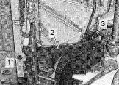
Unscrew bolts "1" and nuts "3" on the left and right and remove the radiator frame cross members "2".
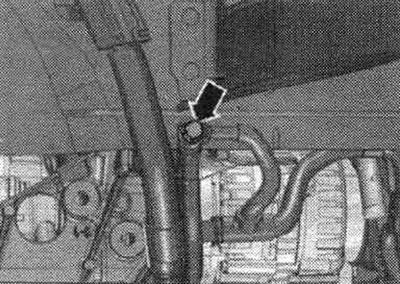
Unscrew the "arrow" nut on the right side member and release the ground cables.
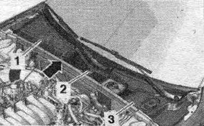
Remove the "arrow" gasket. Remove the water drain box cover.
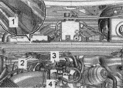
Remove the vacuum pipe "2" from the front wall; to do this, remove the vacuum hose "1" on the back side. Release fuel. main line and the line going to the activated carbon absorber on the air duct tube. Disconnect the plug connector "3" of the el. magnetic valve 1 of the activated carbon canister "N80" and remove the vacuum hose "4". Release the el. magnetic valve 1 of the activated carbon absorber "N80" from the bracket and together with the connected hoses put aside.
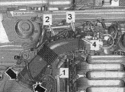
Remove the "arrow" air duct.
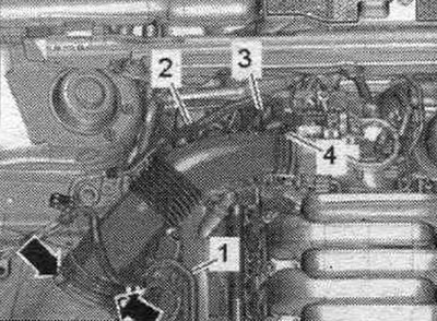
Release fuel. hose "1" from the air tube. Remove vacuum hose "3" from the air duct connection. Remove the air duct tube by loosening clamp "4" and unlocking the "arrow" latches. Ignore "Pos. 2.".
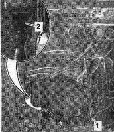
Disconnect vacuum line "1". Remove air intake housing. filter and, if present, disconnect the electrical connector "2" of the air inlet switching valve "N335" on the reverse side.
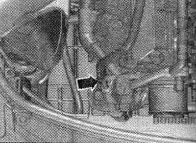
Unscrew the fuel supply. hose from the high pressure pump "arrow" and put it aside.
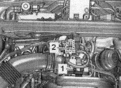
Seal open lines and pipes with clean plugs from the VAS 6122 engine plug kit. If present, disconnect and release vacuum hose "1." Remove coolant hose "2" from the upper coolant pipe by pressing the retaining clip.
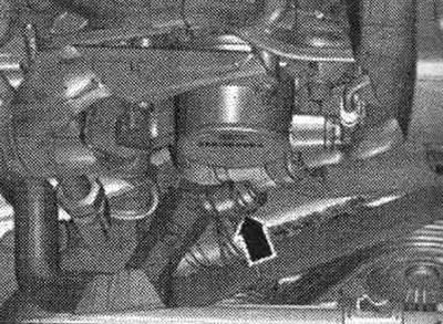
In a car without a coolant circulation pump "V50" and with an independent heater, remove the front right coolant hose from the coolant pipe, to do this, press the fastening bracket "arrow".
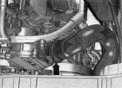
Remove the system hose. cooling from the front coolant pipe, to do this, press the fastening bracket "arrow".
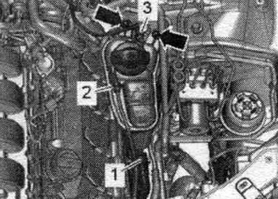
Remove coolant hose "3" from the coolant expansion tank and release it. Unscrew the "arrow" bolts, disconnect the electrical connector of the low coolant level indicator sensor "F66" and move aside the coolant expansion tank with the connected coolant hoses "1" and "2".
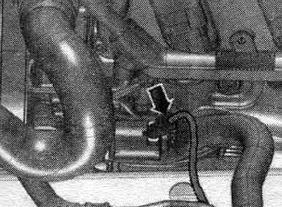
If present, disconnect the "arrow" connector from the power steering pump. Press the hydraulic hose downwards slightly.
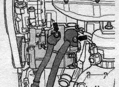
Unscrew the "arrow" bolts and remove the refrigerant lines from the air conditioning compressor. Close open lines and pipes with clean plugs from the VAS 6122 engine plug kit.
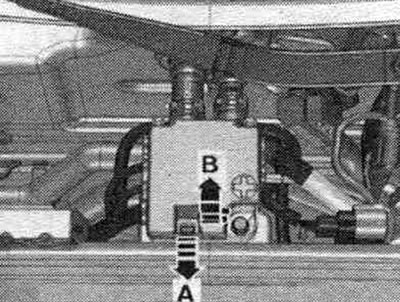
Unlock the lock "arrow A" and open the cover "arrow B".
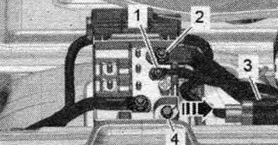
Unscrew nuts "1" and "2" of the electrical wiring. Remove connectors "3" from the bracket and disconnect them. Unscrew bolt "4" and remove branch pipe 2 cl. 30 "TV22" from the "arrow" stretcher.
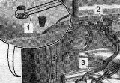
Unlock the clamps on the wheel arch side using a SW 5.5 open-end wrench "pos. 1" and remove the line inlet "2" in an upward direction. Release the wiring harness "3" going to the generator and starter using the lever -80 - 200-.
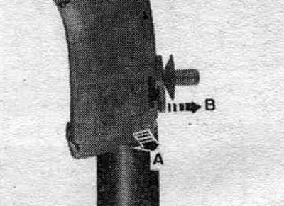
Cable channel - option 1: release the cable channel by unlocking the lock "arrow B" and pulling the cable channel upwards "arrow A".
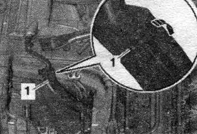
Cable channel - option 2: open the cable channel by unfastening the "arrow" clamp and releasing the wiring harness.
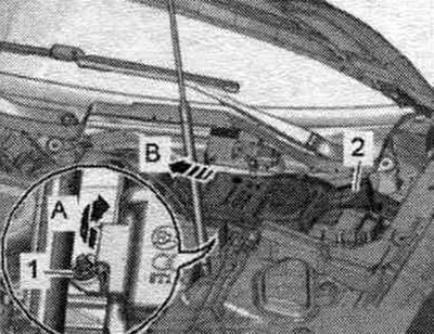
Unscrew the nut "1" and tilt the filler neck "2" of the washer fluid reservoir slightly forward "arrow A". Remove the filler neck with the filler tube from the washer fluid reservoir, passing it through the body opening "arrow B".
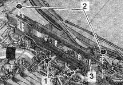
Unscrew bolts "1" and nuts "2" and remove stretcher "3".
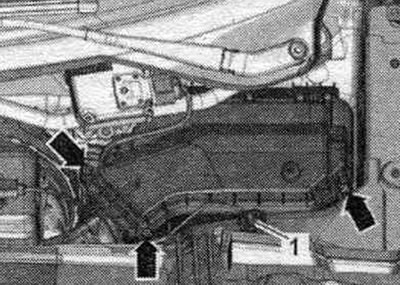
Unscrew the arrow bolts and remove the cover of the motorcycle switching unit. compartment. Unscrew nut "1" and release the wire.
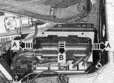
Unlock the "arrow A" fasteners and remove the "arrow B" engine control unit.
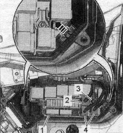
Disconnect (if available) plug connector "2". Disconnect plug connectors "4" and unscrew wire fastening nut "3". Unlock the "arrow" latches and remove the relay and fuse "1" holders. Remove and release the engine wiring harness secured in the engine junction box. compartment.
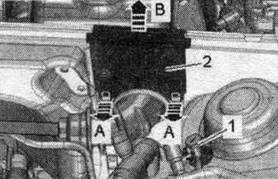
Unlock the clamps "arrow A" and remove the cable guide "2" in the upward direction "arrow B". Loosen the ground bolt "1" and release the wiring harness. Place the wiring harness on the engine and secure the engine control unit from falling out.
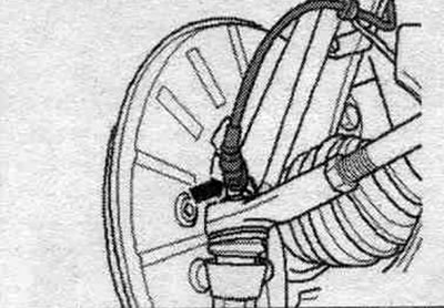
Disconnect the "arrow" plug connector from the front speed sensors on the left and right.
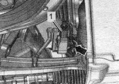
If available, disconnect connectors "1" of the front left vehicle level sensor "G78" and the front right vehicle level sensor "G289" and release the electrical. "Arrow" cable.
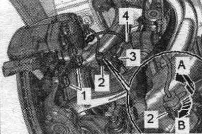
Disconnect plug connector "2" from the bracket by pulling the locking tab back "arrow A" and turning the connector approx. 90° clockwise "arrow B". Release wire "3" and brake hose "4" on the bracket. Unscrew bolts "1" and hang the brake with wire. caliper on the wheel arch. Do not press the brake pedal when the brake is released. support.
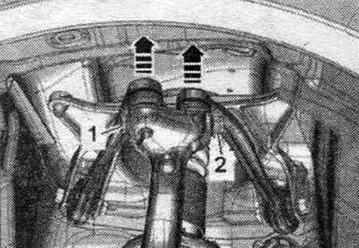
Loosen nut "2" and remove bolt "1." Remove the upper control arm from the wheel bearing housing in the upward direction indicated by the arrows. Repeat the entire process on the other side of the vehicle.
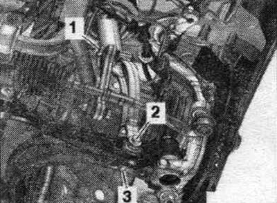
Unscrew the stabilizer bolt "1" on the left and right. Unscrew nut "3" on the left and right. Unscrew bolts "2" last.
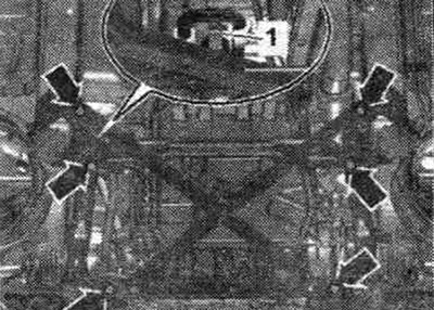
If the engine mounts, steering gear or subframe crosspiece are not installed correctly, the vehicle must not be placed on its wheels. Loosen nut "1" securing the power steering hydraulic line. Loosen the "arrow" bolts and remove the subframe brace. The figure shows the installation. position on a vehicle with dynamic steering.
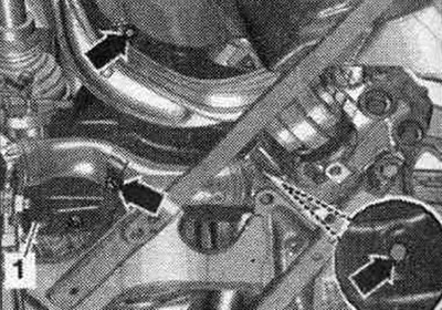
If present, unscrew the "arrow" bolts on the left and right, remove the heat shield "1".
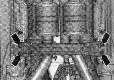
If present, unscrew the arrow bolts and remove the front cross member.
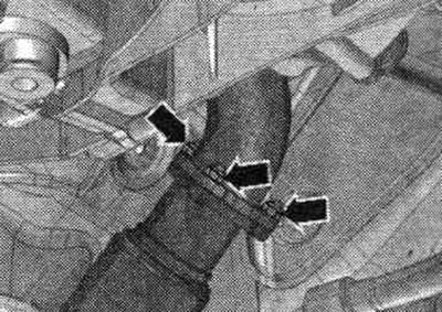
Unscrew the "arrow" nuts of the left front muffler.
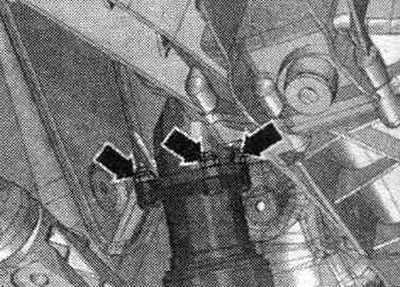
Unscrew the nuts "arrows" of the right front muffler.
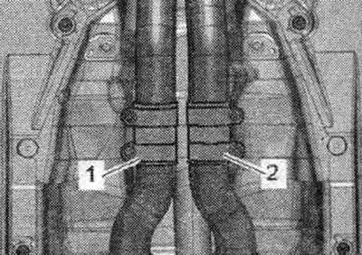
Do not tilt the disconnecting components in the front muffler more than 10°. Loosen and move clamps "1" and "2" back, and remove the left and right front mufflers.
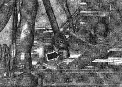
Risk of damage to the coil spring contact of the airbag. The universal joint with the crosspiece should be disconnected from the steering gear only when the front wheels are in the forward position. Do not change the position of the steering wheel and steering gear any further; for this purpose, fix the steering wheel, for example. use tape. Unscrew the "arrow" bolt of the cardan shaft with the crosspiece. Press the universal joint with the crosspiece away from the steering gear and move the joint up until it stops.
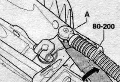
Press the ball joint "A" of the gearbox selector cable with the release lever -80 - 200- from the shift shaft lever "arrow".
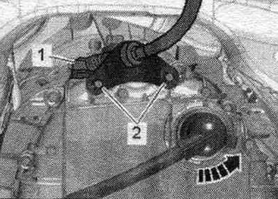
Loosen the "2" stop bolts. Do not bend or kink the gear selector cable. "Pos. 1" and "arrow" should not be taken into account.
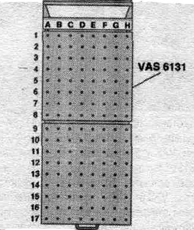
Prepare the lift: Equip the VAS 6131 A lifting table with a set of conductors for Audi "VAS 6131/10", and also add. set "VAS 6131/13" as follows.
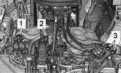
First, screw the fastening elements to the lifting table by hand. Install the lifting table "VAS 6131 A" horizontally. Monitor the level (peephole) on the receiving platform. Place the lifting table "VAS 6131 A" under the power unit. Risk of accident due to unsecured subframe. It is prohibited to unscrew bolts "2" and "3" securing the subframe. Unscrew the bolts "1" of the subframe on the left and right.
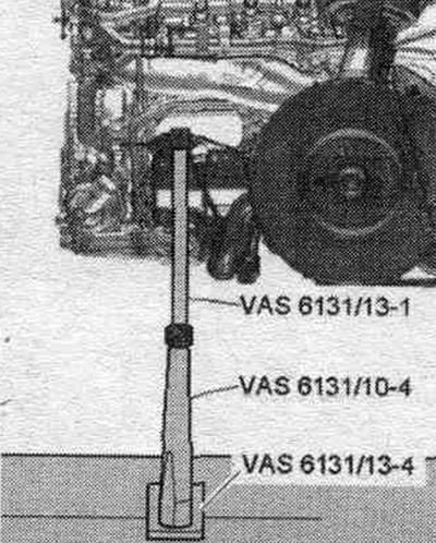
Install conductors from "VAS 6131/10" and "VAS 6131/13" left and right on the front of the subframe, as shown in the picture. Make sure the lead screws are fully screwed in.
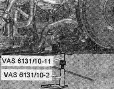
Install conductors from "VAS 6131/10" at the rear left and right on the front threaded connections of the subframe strut, as shown in the figure.
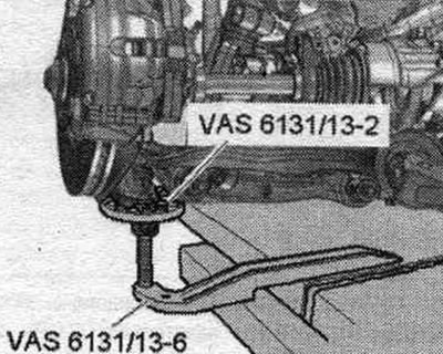
Install conductors from "VAS 6131/13" left and right on the lower part of the wheel hub bearing housing, as shown in the figure.
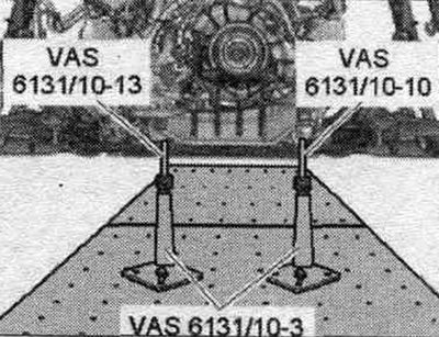
Remove the noise insulation screen clamps from the cross member. Install the fastening elements from "VAS 6131/10" left and right at the rear on the crossbar, as shown in the picture. Turn all the lead screws of the conductors upwards so that all the mounting protrusions enter the mounting points. Screw the support plates of the fastening elements to the lifting table "VAS 6131 A" with a torque of 20 Nm.
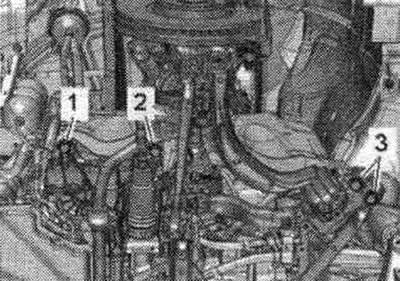
Mark the mounting on the side members with a felt-tip pen. position of the subframe and tunnel crossmember. Loosen bolts "2" and "3" of the subframe crosswise in several stages. "Pos. 1" should not be taken into account.
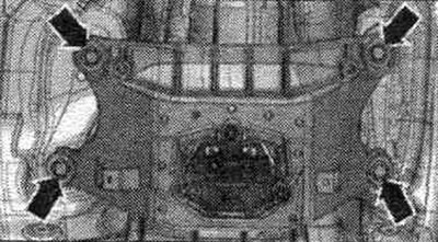
Unscrew the tunnel cross member arrow bolts.
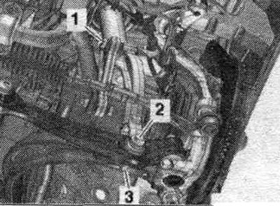
Unscrew bolt "2" on the left and right.
Check that all hoses and pipes between the engine, gearbox, subframe and body have been removed. Remove the power unit with the subframe from the motorcycle. compartment, being careful when lowering it. Raise the engine and gearbox using the VAS 6131 A lifting table. Remove the VAS 6131 A lifting table with the engine/gearbox assembly from underneath the vehicle.
Disconnecting the engine and gearbox multitronic OAW
The engine/gearbox is removed and placed on the VAS 6131 A lifting platform. Remove the electrical connector "1" of the lambda probe after the "G131" catalytic converter from its holder, disconnect it, and place it aside. "Pos. 2, 3, 4" and "arrows" are not taken into account.
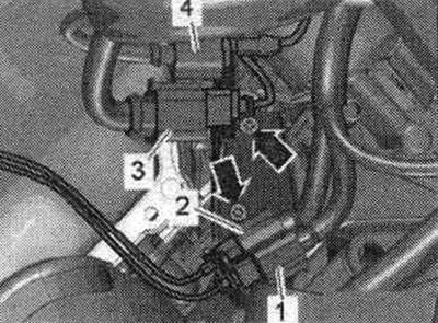
Unscrew the nuts "arrows" and bolts "1" and remove the catalytic converter on the left.
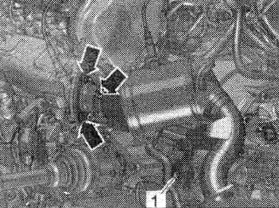
Remove the "1" connector of the lambda probe after the "G130" catalytic converter from the holder and disconnect it. Ignore "Pos. 2, 3, 4" and "arrows".
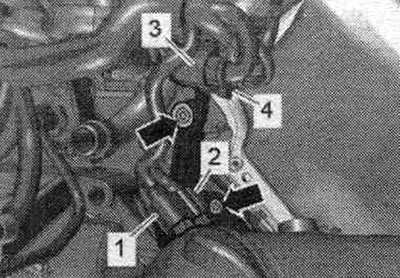
Unscrew the nuts "arrows" and bolts "1" and remove the catalytic converter on the right.
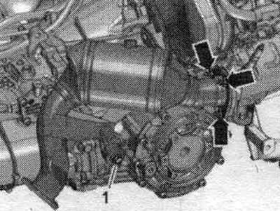
Disconnect plug "2" of engine speed sensor "G28" and move the electrical wire to the side. "Pos. 1" should not be taken into account.
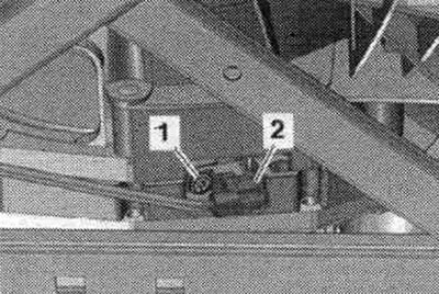
Risk of malfunction of the gearbox control unit (Mechatronik) due to static discharge. Do not touch the gearbox connector contacts with your hands. Disconnect the connector from the gearbox by turning the rotary latch counterclockwise "arrow". Release the wiring. "Pos. 1, 2" do not take into account.
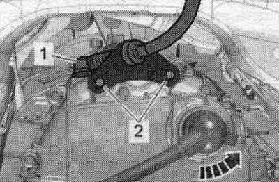
Unscrew the left and right articulated shafts from the shafts with the gearbox flange.
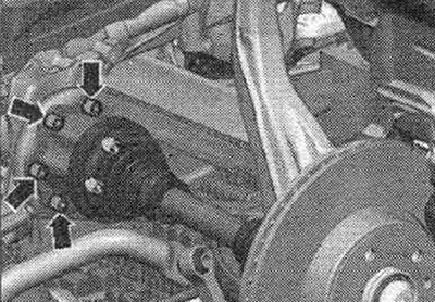
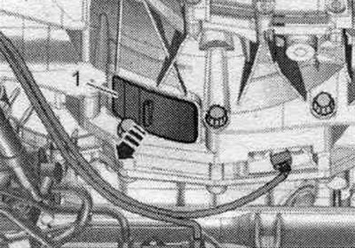
Remove cover "1" from the bottom of the "arrow" gearbox.
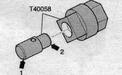
Insert the guide pins of the adapter "T40058" as shown below: the large diameter "arrow 1" faces the engine, the small diameter "arrow 2" faces the adapter.
When unscrewing the driven disk bolts, hold the crankshaft with the T40058 adapter from turning. During the final turn, rotate the crankshaft only in the direction of engine rotation "arrow".
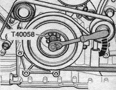
Unscrew the 6 bolts "arrow" of the driven disk, to do this, turn the crankshaft by 60° in the direction of engine rotation.
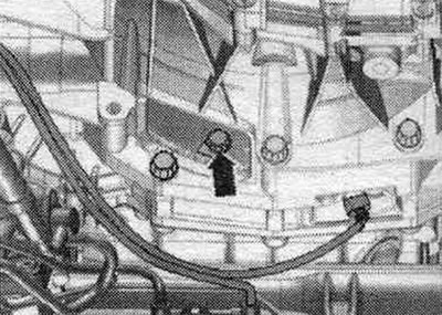
Loosen the ATF line arrow bolt.
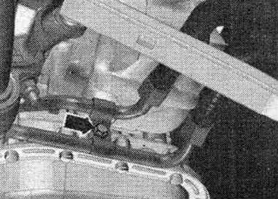
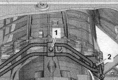
Unscrew bolts "1" and "2", disconnect the ATF lines from the gearbox and tie them up from above. Close open lines and pipes with clean plugs from the plug kit for the "VAS6122" engine.
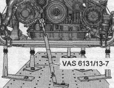
Prepare the lifting table "VAS 6131 A" with a set of fasteners for Audi "VAS 6131/10", additional set "VAS 6131/13" and mounting bracket "VAS 6131/14" as follows. The remaining adapters remain unchanged. Screw in the conductor "VAS 6131/13-7" on the right side of the engine into the threaded hole as shown in the figure. Secure the conductor "VAS 6131/13-7" on a lifting table with a torque of 20 Nm.
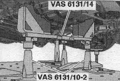
Install conductors from "VAS 6131/10" and the gearbox lock "VAS 6131/14" in front of the checkpoint, as shown in the figure. Turn the right and left lead screws upwards so that the gearbox lock "VAS 6131/14" fits snugly against the gearbox. Screw the support plates of the fastening elements to the "VAS 6131 A" lifting table with a torque of 20 Nm.
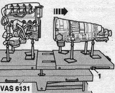
Loosen starter bolts "1" and "2." Push the starter away from the gearbox and leave it in its mounting position. Loosen the remaining bolts "3...11" securing the engine to the gearbox. Ignore "Pos. A". Loosen the clamping bolts "1" on the side of the lifting table "VAS 6131 A" and move the rear platform with the gearbox back "arrow".