



Removal and installation the left and right timing chain covers
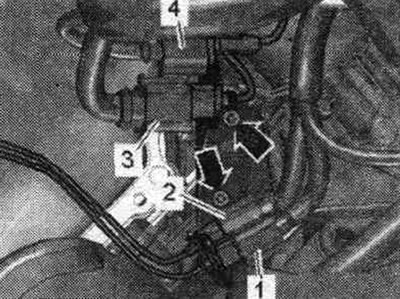
When reinstalling, install all cable ties there. where they were originally installed. Remove the rear engine cover -upper arrows-. Cars without syst. secondary air supply: remove the front wall of the water drainage box. Vehicles with secondary air injection system: Remove the corresponding secondary air injection combination valve.
Left drive chain cover: Remove electrical connectors "1...4" from the bracket and set aside. "Arrows" should not be taken into account. Release the electrical wires.
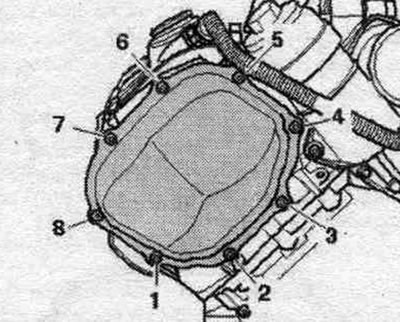
Unscrew bolts "1...8" and remove the left cover of the drive chain.
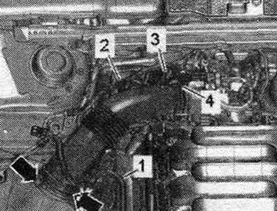
Right timing chain cover: Release fuel. line "1" and wire "2" to the activated carbon absorber on the air duct. Remove vacuum hose "3" from the air duct connection. Remove the air duct tube by loosening clamp "4" and unlocking the "arrow" clamps.
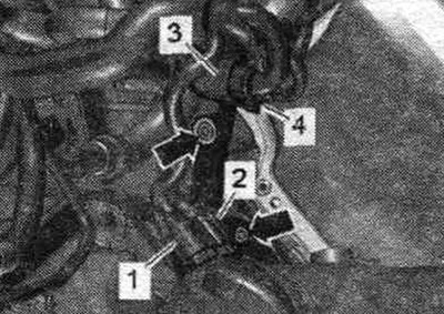
Remove electrical connectors "1...4" from the bracket and set them aside. "Arrows" should not be taken into account.
Unscrew bolts "1...8" and remove the right drive chain cover.
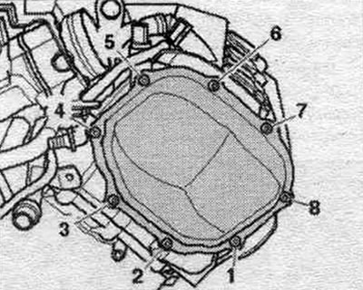
Installation
Remove any remaining sealant from the timing chain covers, cylinder block and cylinder head, for example, using a rotating brush attachment with plastic bristles. Clean the seating surfaces; there should be no oil or grease on them. Observe the expiration date of the sealant. Cut off the tube tip along the front mark (opening diameter approx. 2 mm). Risk of blockage of the system channels. lubrication when there is excess sealant. The sealant bead should not be thicker than the specified size. Apply a bead of "arrow" sealant to the clean seating surface of the left timing chain cover as shown in the figure. Sealant bead thickness: 2.5 mm. Timing chain covers must be installed within 5 minutes of sealant application.
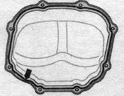
Insert the left timing chain cover and tighten the bolts. Apply a bead of "arrow" sealant to the clean seating surface of the right timing chain cover as shown in the figure. Thickness of sealant bead: 2.5 mm. Insert the right timing chain cover and tighten the bolts. Installation in reverse order. Secure all hose connections with hose clamps of the appropriate standard.
Car without system. secondary air supply: install the front wall of the water drainage box. Vehicles with secondary air injection system: Install a combined secondary air injection valve.
Camshaft chain drives
Left camshaft timing chain
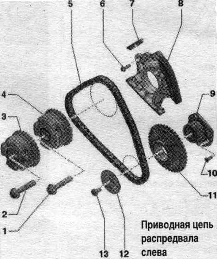
1/2. Bolt: replace, 80 Nm + 90° (tighten further).
3. Exhaust camshaft phase shifter: marked "Exhaust".
4. Intake camshaft phase shifter; "Intake" marking.
5. Left camshaft timing chain: Mark the direction of travel with paint before removing.
6. Bolt: 9 Nm.
7. Crawler.
8. Left camshaft chain tensioner.
9. Chain drive sprocket bracket.
10. Bolt: replace, 8 Nm + 45° (tighten further).
11. Drive sprocket for camshaft drive chain on the left.
12. Adjusting washer of chain drive sprocket.
13. Bolt: replace, 6 Nm + 60° (tighten further).
Right camshaft timing chain
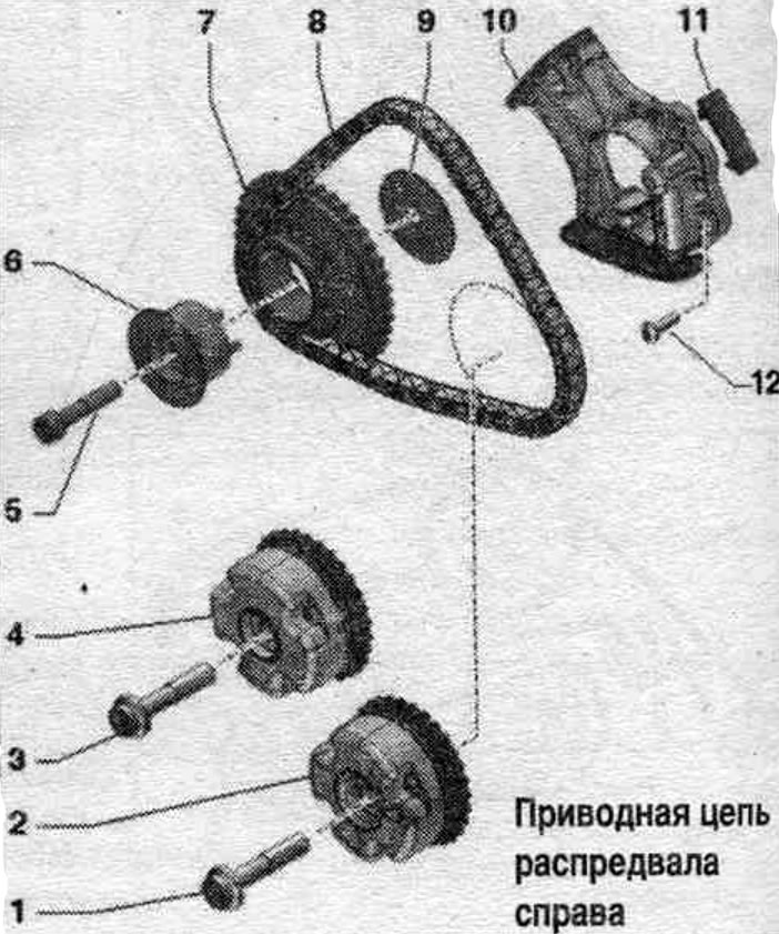
1. Bolt: replace, 80 Nm + 90° (tighten further).
2. Exhaust camshaft phase shifter: marked "Exhaust".
3. Bolt: replace. 80 Nm + 90° (tighten further).
4. Intake camshaft phase shifter: - marked "Intake".
5. Bolt: replace, 30 Nm + 90° (tighten further).
6. Timing chain sprocket bracket: for camshaft timing chain on the right, asymmetrical design.
7. Drive sprocket for camshaft drive chain on the right.
8. Right camshaft timing chain: Mark the direction of travel with paint before removing.
9. Timing chain sprocket adjusting washer: for camshaft drive chain on the right, asymmetrical design.
10. Timing chain tensioner for the camshaft on the right.
11. Crawler.
12. Bolt: 9 Nm.
Removal the chains from the camshafts
The following description assumes that the camshaft timing chains remain on the engine. Remove the corresponding cylinder head cover. Remove the camshaft chain guards on the left and the reference. Remove noise insulation screens "1" and "2".
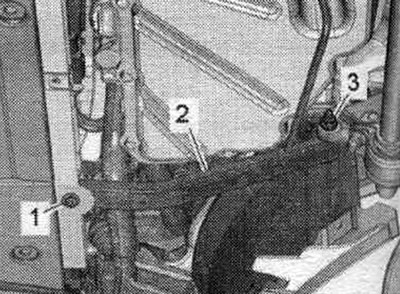
Cars without coolant recovery pump "V51": Unscrew bolt "1" and nut "3" and remove left spacer "2" of radiator frame.
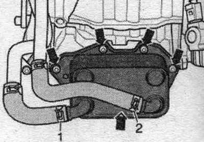
Install a device for pumping and collecting oil under the engine. Unscrew the "arrow" bolts and tie the oil radiator with the connected coolant hoses "1" and "2" to the side.
Vehicles with coolant recirculation pump "V51": Remove the coolant recovery pump "V51".
All
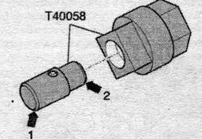
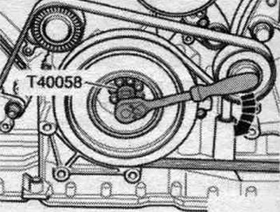
Insert the guide pins of the adapter "T40058" as shown below: large diameter "arrow 1" facing the engine, small diameter "arrow 2" facing the adapter.
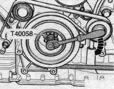
Turn the cardan shaft using the adapter "T40058" in the direction of engine rotation "arrow" to "TDC".
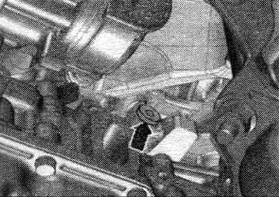
Unscrew the threaded plug "arrow" for the "TDC" mark from the cylinder block.
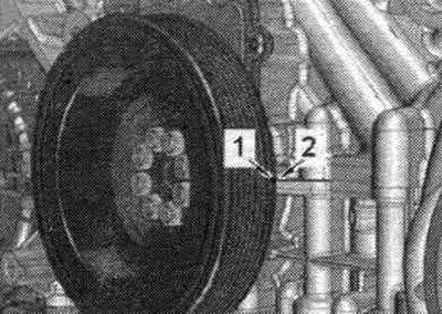
When the engine is installed, the crankshaft fixing hole is barely visible. Therefore, turn the engine so that the small notch "1" on the torsional vibration damper to the left of the direction of travel on the left is located opposite the butt weld on the housing "2" between the cylinder block and the camshaft frame. This makes it easier to tighten the "T40069" retaining bolt. The mark on the vibration damper is for reference only. The exact position of the "TDC" mark can only be achieved by rotating the "T40069" locking screw.
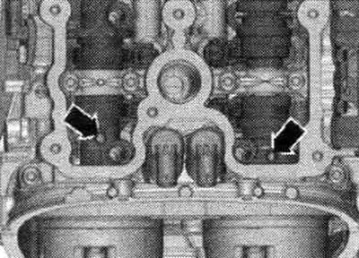
The threaded holes "arrows" in the camshafts must point upwards.
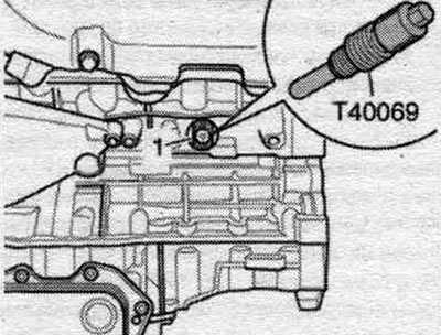
Screw the "T40069" fixing bolt into the hole with a torque of 20 Nm; if necessary, to completely center the bolt, turn the crankshaft slightly in both directions.
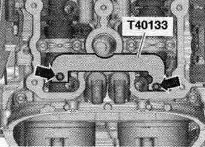
Install the camshaft retainers "T40133" on both cylinder heads and tighten to 25 Nm "arrows". The illustration shows the left cylinder head.
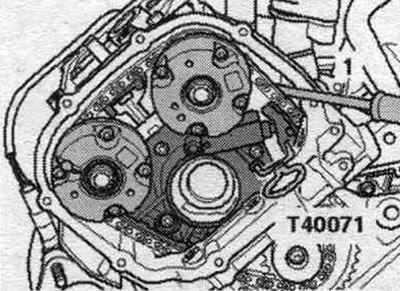
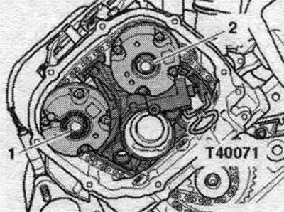
Use screwdriver "1" to move the left camshaft chain tensioner sliding bar inward until it stops and secure the tensioner with clamp "T40071." The chain tensioner is equipped with an oil damper, so apply pressure gradually and evenly.
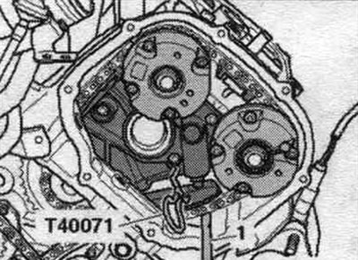
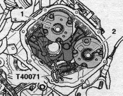
Use screwdriver "1" to move the sliding bar of the right camshaft chain tensioner, turn it inward until it stops, and secure the tensioner with clamp "T40071." The chain tensioner is equipped with an oil damper, so apply pressure gradually and evenly.
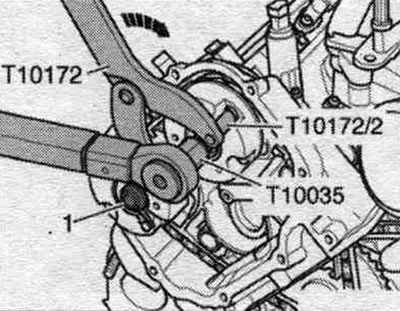
Risk of damage to the camshaft. To loosen the bolts "1" of the camshaft phase shifter, do not under any circumstances use the camshaft locking tool "T40133" as a counter support.
Mark mont. phase shifter position for reinstallation. To prevent small parts from accidentally falling into the engine through the opening in the drive chain box, cover the opening with a clean rag. Unscrew bolts "1" and "2" on the cylinder head on the left and remove both phase shifters.
Mark mont. phase shifter position for reinstallation. Unscrew bolts "1" and "2" on the cylinder head on the right and remove both phase shifters.
Installation
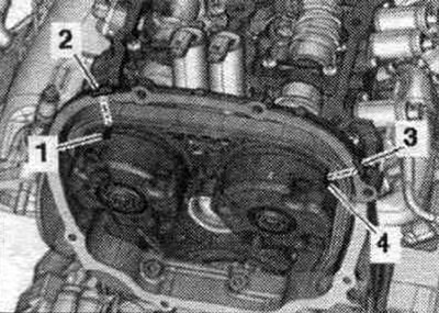
Replace bolts that were tightened with additional tightening. Replace the seal. tDC threaded plug ring. Risk of damage to valves and piston crowns. When turning the camshaft, none of the crankshaft pistons should be at TDC. The chain drive is installed. The crankshaft is locked with the locking bolt "T40069" in the "TDC" position. The camshaft retainers "T40133" are installed on both cylinder heads and tightened to 25 Nm "arrows". The illustration shows the left cylinder head. During the following repair work, the camshaft adjusters may only be installed in such a way that the grooves "1" and "4" are opposite the installation windows (polished surfaces) "2" and "3".
Install the camshaft phase shifters on the left cylinder head according to the markings made during removal. Install the left drive chain onto the drive sprocket and phase shifter and tighten bolts "1" and "2." Both phase shifters should be able to rotate on the camshaft; they should not be warped. Remove locking pin "T40071".
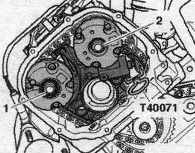
Install the camshaft phase shifters on the right cylinder head according to the markings made during removal. Install the right drive chain onto the drive sprocket and phase shifter and tighten bolts "1" and "2." Both phase shifters should be able to rotate on the camshaft; they should not be warped. Remove locking pin "T40071".
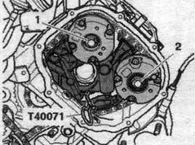
Place the counter support "T10172" with the pin "T10172/2" against the phase shifter of the left intake camshaft. The second mechanic must maintain the pre-tension of the camshaft drive chain by pressing the counter support in the direction of the arrow. Tighten the bolts as follows, while the phase shifter is still pre-tensioned.
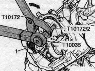
1. Pre-tighten the bolt to the intake camshaft to a torque of 80 Nm. 2. Pre-tighten bolt "1" to the exhaust camshaft to a torque of 80 Nm.
Install the support "T10172" with the pin "T10172/2" on the phase shifter of the right exhaust camshaft. The second mechanic must maintain the pre-tension of the camshaft drive chain by pressing the counter support in the direction of the arrow. Tighten the bolts as follows, while the phase shifter is still pre-tensioned.
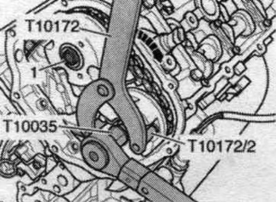
1. Pre-tighten the bolt to the exhaust camshaft to a torque of 80 Nm. 2. Pre-tighten bolt "1" to the intake camshaft to a torque of 80 Nm.
Remove the camshaft retainers "T40133" from both cylinder heads "arrows". The illustration shows the left cylinder head. Tighten the camshaft adjuster bolts on the left cylinder head as follows.
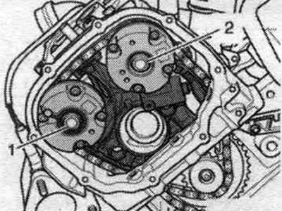
1. Tighten bolt "1" to the intake camshaft to the final torque. 2. Tighten bolt "2" to the exhaust camshaft to the final torque.
Tighten the phase shifter bolts on the right cylinder head as follows.
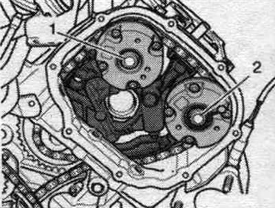
1. Tighten bolt "1" to the intake camshaft to the final torque. 2. Tighten bolt "2" to the exhaust camshaft to the final torque.
Unscrew the locking bolt "T40069". Turn the crankshaft using the adapter "T40058" 2 turns in the direction of engine rotation "arrow" so that the crankshaft is again in the "TDC" position. If "TDC" has been passed by mistake, turn the crankshaft back 30° and set it to "TDC" again.
The threaded holes "arrows" in the camshafts must point upwards. Install the camshaft retainers "T40133" on both cylinder heads and tighten to 25 Nm "arrows". Screw the locking bolt "T40069" straight into the hole. The fixing bolt "T40069" must fit into the hole on the crankshaft "1", otherwise repeat the adjustment. Remove the camshaft locking pins on both cylinder heads. Unscrew the "T40069" locking bolt. Reinstall in reverse order. Install the timing chain guards on the left and right. Install the cylinder head covers. Install the "V51" coolant recirculation pump. Install the oil cooler. Install the radiator frame spacer. Installation of front noise insulation.
Timing chain
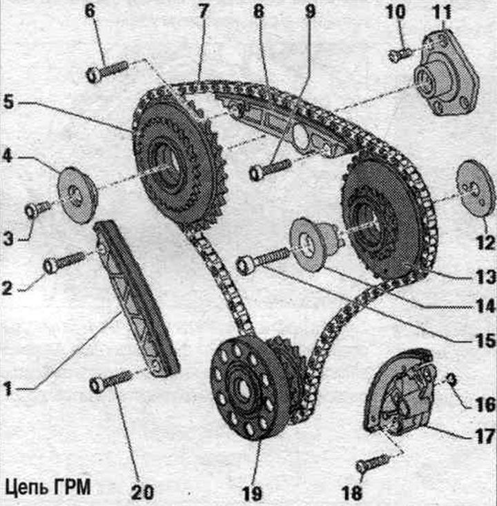
1. Dampener bar.
2. Bolt: replace, 10 Nm + 90° (tighten further).
3. Bolt.
4. Adjusting washer of chain drive sprocket.
5. Chain drive sprocket for the drive chain on the left.
6. Bolt: replace, 10 Nm + 90° (tighten further).
7. Chain drive of the control mechanism: before removing, mark the direction of movement with paint.
8. Dampener bar.
9. Bolt: replace, 10 Nm + 90° (tighten further).
10. Bolt.
11. Timing chain sprocket bracket: for camshaft timing chain on the right, asymmetrical design.
12. Adjusting washer: asymmetric design.
13. Timing chain drive sprocket on the right.
14. Chain drive sprocket bracket: asymmetric design.
15. Bolt.
16. O-ring: Replace.
17. Chain tensioner.
18. Bolt: 9 Nm.
19. Crankshaft.
20. Bolt: replace, 10 Nm + 90° (tighten further).
Mounting position of the drive chain sprocket bearing housing on the right
The dowel pins in the bearing cap bolts "3" of the right camshaft drive sprocket must fit into the hole in the dowel washer "1" and the cylinder block.
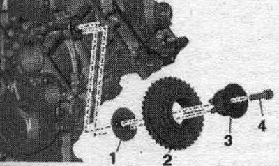
2. Drive sprocket for camshaft drive chain on the right. 4. Bolt.
[This publication is borrowed from the resource: AUDImanual.ru]