
Table of contents: Cylinder head ↓ Removal and installation the left… ↓ Removal and installation the right… ↓ Removal and installation the… ↓
Cylinder head
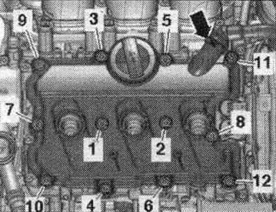
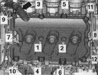
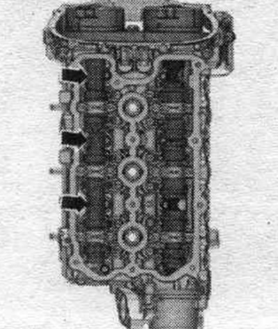
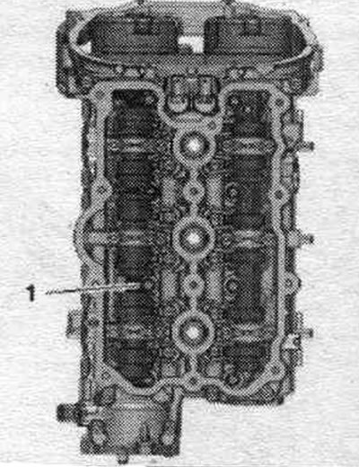
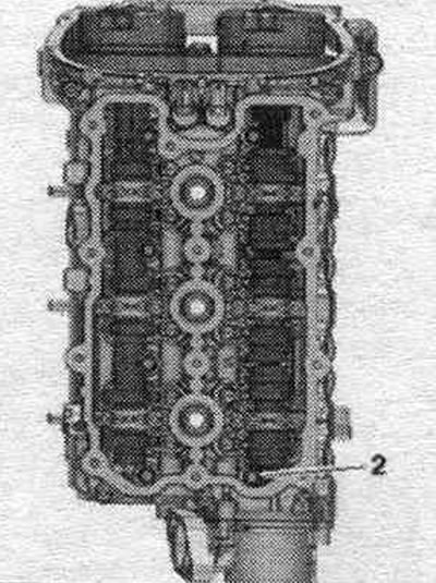
The figure shows the cylinder head of the 2nd row of cylinders (left).
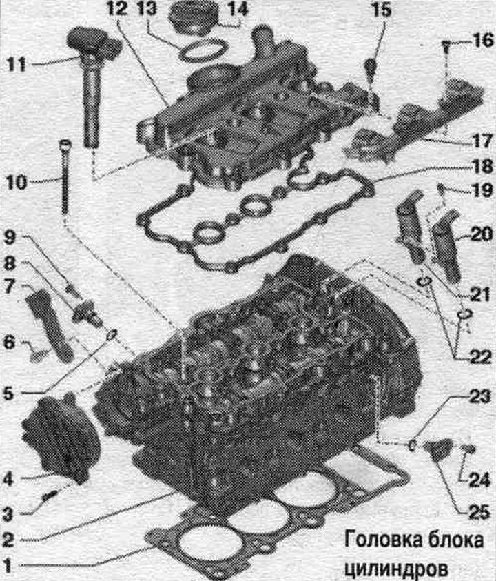
1. Cylinder head gasket: installation position: Cylinder head part number; after replacement, change the coolant and oil.
2. Cylinder head: after replacement, change the coolant and oil.
3. Bolt.
4. Vacuum pump.
5. Sealing ring: replace.
6. Bolt: 20 Nm.
7. Engine suspension eye.
8. Intake camshaft Hall sensor: cylinder bank 1 (right), Hall sensor "G40"; cylinder bank 2 (left), Hall sensor 2 "G163".
9. Bolt: 9 Nm.
10. Bolt: replace; tighten in 3 stages: 1) tighten to 40 Nm; 2) turn 90°; 3) turn 90°.
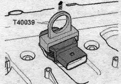
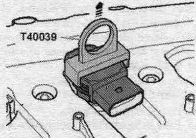
11. Coil: remove using puller "T40039".
12. Cylinder head cover.
13. Gasket: Replace if damaged or loose.
14. Lid.
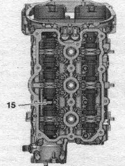
15. Bolt: replace if seal is damaged.
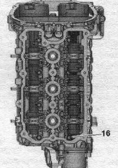
16. Bolt.
17. Plug bar: for coils.
18. Cylinder head cover gasket: replace if damaged or not tightly fitted.
19. Bolt: 2.5 Nm.
20. Electric. mag. valve syst. valve timing system on the exhaust side: Cylinder bank 1 (right) Valve 1 of the valve timing system on the exhaust side "N318". Cylinder bank 2 (left) Valve 2 of the valve timing system on the exhaust side "N319".
21. Electric. mag. valve syst. variable valve timing system on the intake side: Cylinder bank 1 (right) Valve 1 variable valve timing system "N205". Cylinder bank 2 (left) Valve 2 variable valve timing system "N208".
22. O-ring seal: replace.
23. Sealing ring: replace.
24. Bolt: 9 Nm.
25. Exhaust camshaft Hall sensor: Bank 1 (right) Hall sensor 3 "G300", Bank 2 (left) Hall sensor 4 "G301".
Left cylinder head cover - last and tightening torque
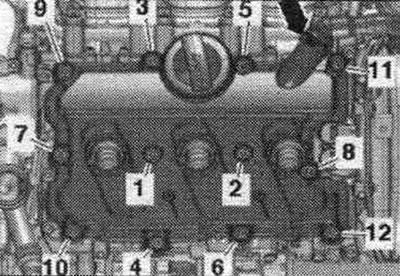
Tighten the bolts in sequence. "1...12" with a torque of 9 Nm.
Right cylinder head cover - sequence and tightening torque
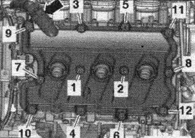
Tighten the bolts in sequence. "1...12" with a torque of 9 Nm.
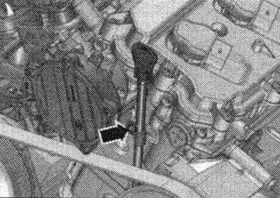
Oil dipstick guide tube - tightening torque
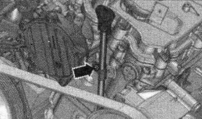
Tighten the arrow bolt to 9 Nm.
Removal and installation the left cylinder head cover
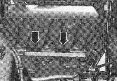
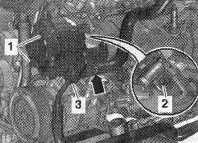
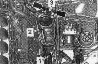
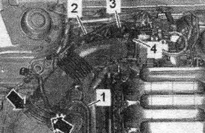
Remove the motor covers. compartment "arrow". Unscrew the "arrow" bolts. Disconnect the electrical connector of the low coolant level indicator sensor "F66" and set aside the coolant expansion tank with the connected hoses "1, 2, 3".
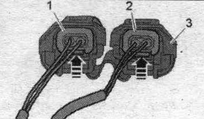
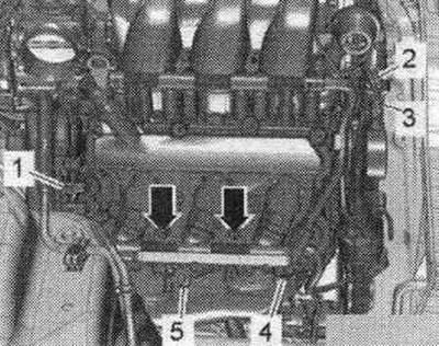
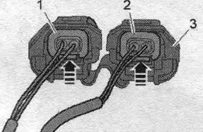
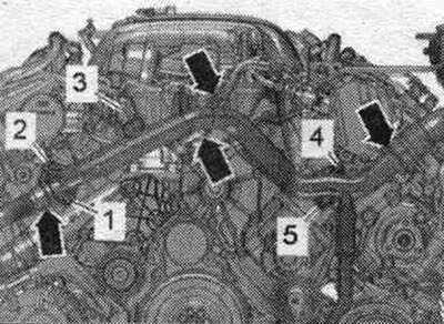
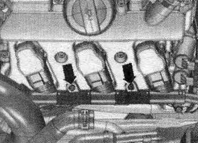
Unscrew the "arrow" bolts on the cylinder head on the left and disconnect the electrical connectors from the coils. Disconnect electrical connector "1" of Hall sensor 2 "G163" and "4" of Hall sensor 4 -G301 -. Unscrew bolt "5" of the ground cable. "Pos. 2" should not be taken into account. Disconnect electrical connectors "1" of valve 1 of the camshaft phase control system "N205" and valve 1 of the exhaust camshaft phase control system "N318" by squeezing the connector latches and removing both connectors together.
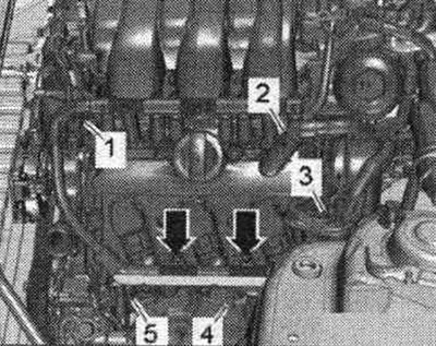
Connector "3" (depending on the configuration) electrical connectors "1" and "2" of the system valves. the timing chain adjustment is designed to prevent the connectors from being mixed up and should not be separated from them. Set the wiring harness aside.
Remove the coils using the "T40039" puller.
Remove the system hose. crankcase ventilation "arrow", for which press the release buttons. Unscrew the bolts in sequence. "12...1" and remove the left cylinder head cover.
Installation
Installation in reverse order. Replace a damaged cylinder head gasket. Replace the cylinder head cover bolts if the gasket is damaged. Clean the seating surfaces; there should be no oil or grease on them. Tighten the left cylinder head cover bolts.
Removal and installation the right cylinder head cover
Remove the motor covers. "Arrow" compartment. Remove the "Arrow" air duct.
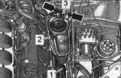
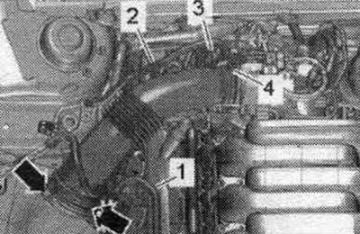
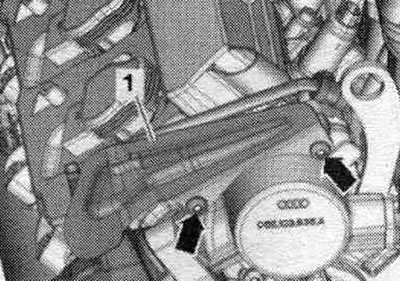
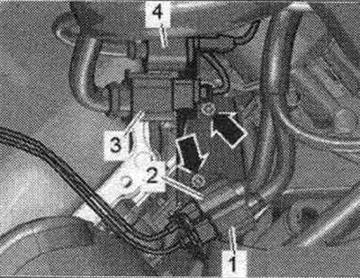
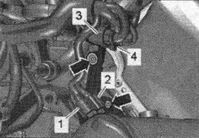
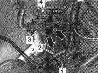
Release fuel. line "1" and wire "2" to the activated carbon absorber on the air duct. Remove vacuum hose "3" from the air duct connection. Remove the air duct tube by loosening clamp "4" and unlocking the "arrow" clamps.
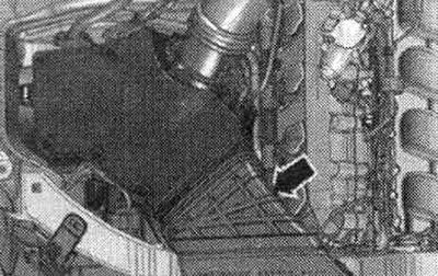
Disconnect vacuum line "1". Remove air intake housing. filter and, if present, disconnect the electrical connector "2" of the air inlet switching valve "N335" on the reverse side.
Unscrew the "arrow" bolts on the right cylinder head and disconnect the electrical connectors from the coils.
Disconnect electrical connector "5" of Hall sensor 3 "G300". Ignore "Pos. 2, 3, 4". Disconnect electrical connectors "1" of valve 1 of the camshaft phase control system "N205" and valve 1 of the exhaust camshaft phase control system "N318" by squeezing the connector latches and removing both connectors together.
Connector "3" (depending on the configuration) electrical connectors "1" and "2" of the system valves. the timing chain adjustment is designed to prevent the connectors from being mixed up and should not be separated from them. Push the wire harness aside.
Remove the coils using the "T40039" puller.
Remove the system hose. crankcase ventilation "arrow", for which press the release buttons. Unscrew the bolts in sequence. "12...1" and remove the right cylinder head cover.
Installation
Installation in reverse order. Replace a damaged cylinder head gasket. Replace the cylinder head cover bolts if the gasket is damaged. Clean the seating surfaces; there should be no oil or grease on them. Tighten the right cylinder head cover bolts.
Removal and installation the cylinder head
The engine is installed. The following describes the simultaneous removal of both cylinder heads. If you only need to remove one cylinder head, you can skip the steps for the unneeded cylinder head. Relieve fuel pressure in the high pressure sector. Remove the upper coolant pipe. Remove the poly V-belt. Remove the lower part of the air intake. Disconnect the plug connectors from the injection nozzles. Remove the camshaft chain protective covers on the left and right.
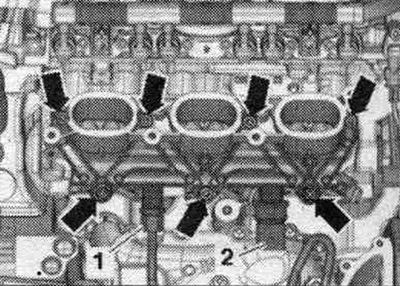
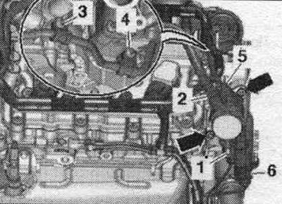
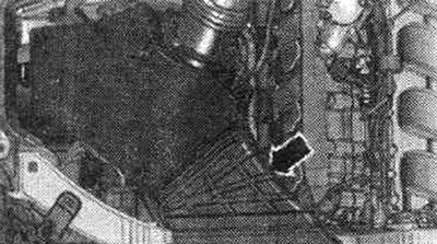
Car without system. secondary air supply: Remove the left front muffler. Unscrew the "arrow" nuts and bolt "1". Remove the left catalytic converter from the exhaust manifold and set it aside. For better understanding of the montage. the position is shown with the engine removed. Removing the right front muffler.
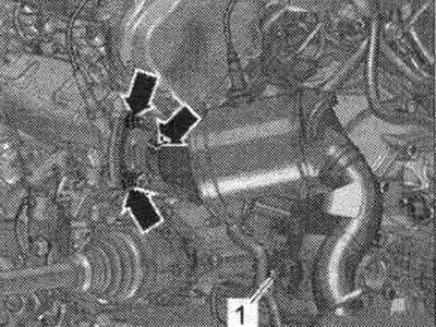
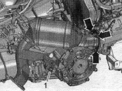
Unscrew the "arrow" nuts and bolt "1", put the catalytic converter aside.
All
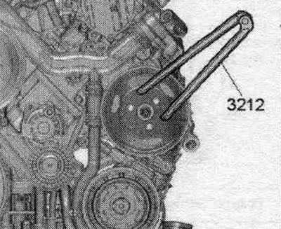
Unscrew the "arrow" bolts of the servo pump poly V-belt pulley; to do this, use a 2-hole "3212" wrench as a counter-support.
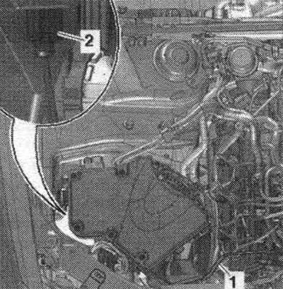
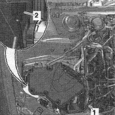
Remove bolts "1" and "2" and place the power steering pump aside. The figure shows the installation. position on a vehicle with dynamic steering. "Pos. 3" and "arrow" should not be taken into account.
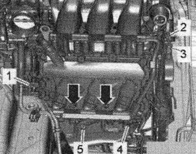
Disconnect connector "3" of coolant temperature sensor "G62". Loosen bolts "1,2,4,5" of the front coolant pipe. Ignore the arrows.
Remove the protective cover "1" of the high-pressure line "arrow".
Relieve fuel pressure in the high pressure sector. Unscrew fastener "1" and union nuts "2" and "3". Unscrew the "arrow" bolts of the holders and remove the high-pressure line.
Unscrew the fastening "2" and move the fuel supply line away. highway to the side. Disconnect plug connectors "1" and "6". Ignore "Pos. 3, 4, 5" and "arrows".
Disconnect the electrical connections on the right and left of the "arrow" from the actuators of the system. adjusting the timing phases. Unscrew bolts "1" and "2" and release the wiring harness. Remove the cylinder head cover.
Disconnect electrical connector "3" of the Hall sensor "G40" on the right cylinder head. Loosen bolt "4" of the ground cable. "Pos. 1, 2, 5" do not take into account. Remove the camshaft chain guards on the left and right.
Unscrew the "arrow" bolts and remove the left connector holder. "Pos. 1, 4" do not take into account.
Unscrew the arrow bolts and remove the right connector bracket. "Pos. 1, 4" do not take into account.
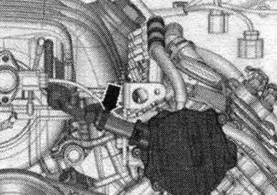
Unscrew the "arrow" bolt and remove the oil dipstick guide tube.
Disconnect the vacuum hose from the "arrow" vacuum pump and release it.
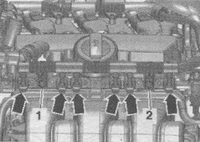
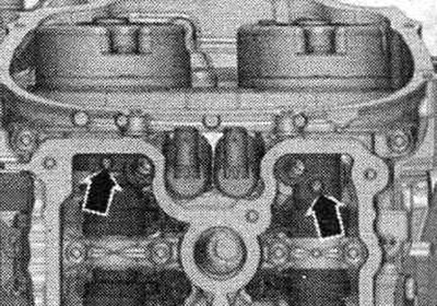
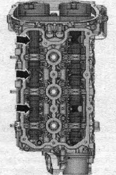
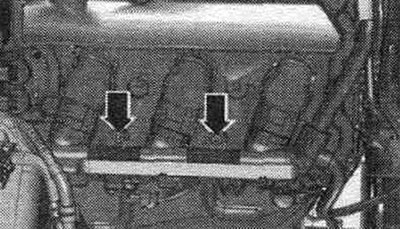
Unscrew the "arrow" bolts behind the cylinder head: left cylinder head: 3 bolts; right cylinder head: 4 bolts.
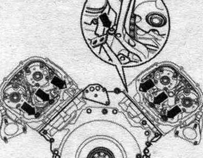
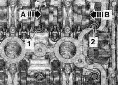
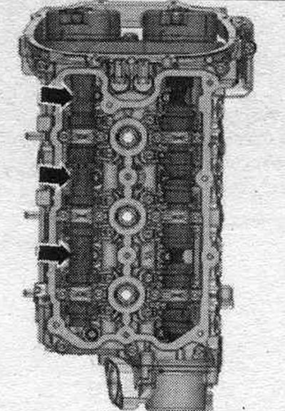
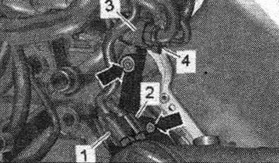
The intake camshaft lobes partially obstruct access to the cylinder head bolts; "1" and "2" are shown as examples. To remove bolt "1," the sliding part of the camshaft must be pushed in the direction of arrow A using a plastic wedge. To remove bolt "2," the sliding part of the camshaft must be pushed in the direction of arrow B using a plastic wedge. The sliding part of the camshaft can only be moved during the main part of the stroke; that is, the lever of the sliding part must not be loaded by the force of the cam. Therefore, to loosen the cylinder head bolts, proceed as described in the following work instructions. Otherwise, damage may occur. The movable part of the camshaft must not be moved by thin bridges.
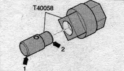
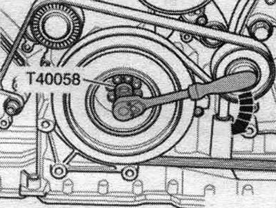
Insert the guide pins of the adapter "T40058" as shown below: large diameter "arrow 1" facing the engine, small diameter "arrow 2" facing the adapter.
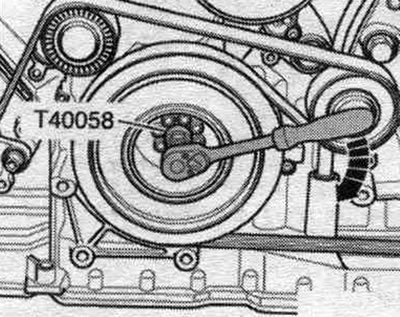
Turn the crankshaft with the adapter "T40058" in the direction of engine rotation "arrow" until the camshaft position shown in the following figures is reached.
The "arrow" notches on the exhaust camshaft should point towards the outside of the engine, as shown in the figure.
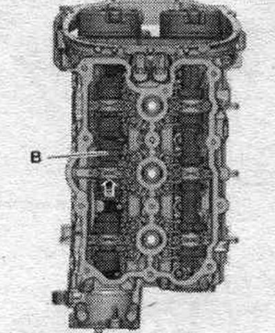
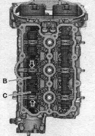
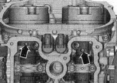
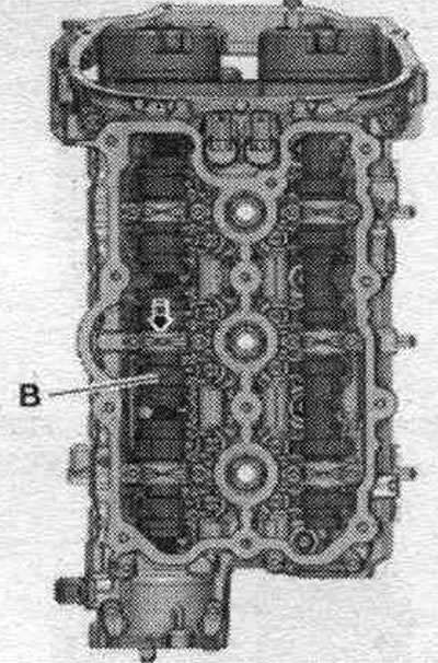
Left cylinder head: Move the unloaded movable part of the camshaft "B" in the "direction of the arrow" until it stops.
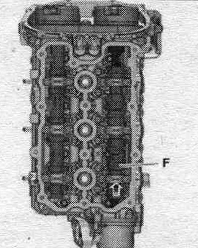
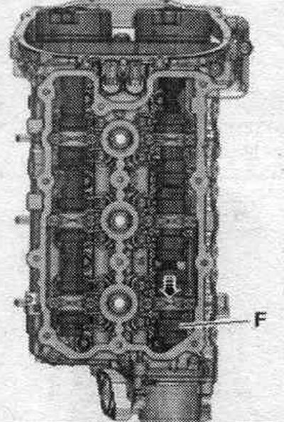
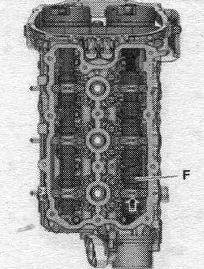
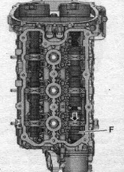
Right cylinder head: Move the unloaded movable part of the camshaft "F" in the "direction of the arrow" until it stops.
All
Turn the crankshaft using the adapter "T40058" in the direction of engine rotation "arrow" by 1 revolution.
The threaded holes "arrows" in the camshafts must point upwards.
Left cylinder head: Unscrew bolt "1" and remove.
Right cylinder head: Unscrew bolt "2" and remove.
All
Turn the crankshaft using the adapter "T40058" in the direction of engine rotation "arrow" by 1 revolution.
The "arrow" notches on the exhaust camshaft should point towards the side of the engine.
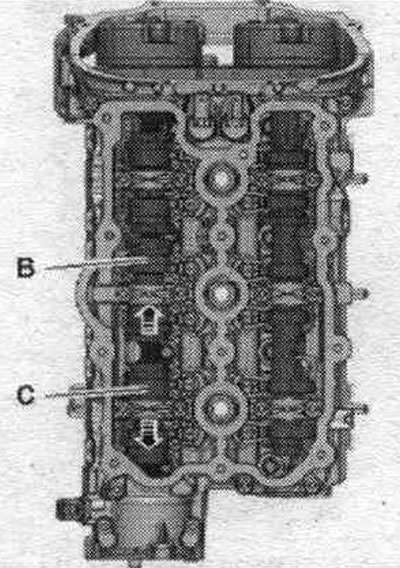
Left cylinder head: Move the unloaded moving parts of the camshaft "B" and "C" "in the direction of the arrow" until they stop.
Right cylinder head: Move the unloaded movable part of the camshaft "F" in the "direction of the arrow" until it stops.
All
Turn the crankshaft with the adapter "T40058" in the direction of engine rotation "arrow" by 1 turn. The threaded holes "arrows" in the camshafts must point upwards. Remove the chains from the camshafts. Even if the chain is removed from only one cylinder head, it is prohibited to turn the crankshaft.
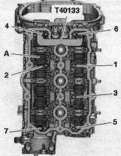
Left cylinder head: Unscrew and remove bolts "3...9", for which correspondingly move the unloaded moving part "A" of the camshaft. Remove the cylinder head.
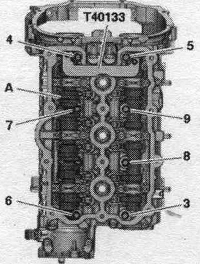
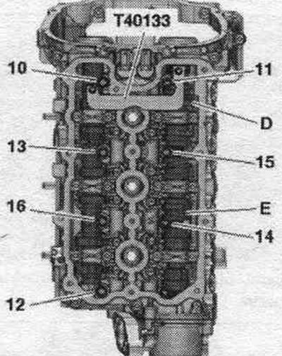
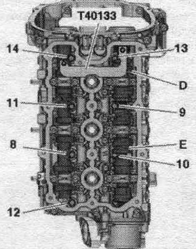
Right cylinder head: Unscrew and remove bolts "10...16", for which move the unloaded moving parts "D" and "E" of the camshaft accordingly. Remove the cylinder head.
Installation
Caution! Risk of damage to the sealing surface. Carefully remove any remaining sealant from the cylinder head and cylinder block. Avoid creating long scratches or burrs. Risk of damage to the cylinder block. There should be no oil or coolant in the blind holes of the cylinder head mounting flanges. Risk of a cylinder head gasket leak. Carefully remove any remaining sanding and grinding material. The new cylinder head gasket should be removed from the packaging immediately before installation. To prevent damage to the silicone layer and the grooves of the cylinder head gasket, handle the gasket with particular care. Risk of damage to open valves. When installing a replacement cylinder head, remove the plastic base to protect the exposed valves only when it comes into direct contact with the cylinder head. There is a risk of damage to the valves and piston crowns after working on the valve train. To ensure that no valves are touching the cylinder head during operation, carefully rotate the engine at least 2 revolutions. Replace any bolts that were overtightened. Replace self-locking nuts, lip seals, gaskets and seals. rings. Consider different sealants for cylinder head sealing surfaces and bolts. Before installing a replacement cylinder head, lubricate the mating surfaces between the hydraulic lifters, rocker arms, and camshaft bearing housing with oil. Secure all hose connections with hose clamps of the appropriate standard. If the cylinder head or cylinder head gasket was replaced, then the coolant and oil must be replaced.
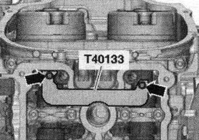
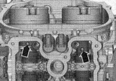
Before installing the cylinder head, set the crankshaft and camshafts to "TDC". To do this, install the camshaft retainers "T40133" on both cylinder heads and tighten them to 25 Nm "arrows". The camshaft retainer "T40133" is installed correctly if the holes facing the cylinder head bolts remain free.
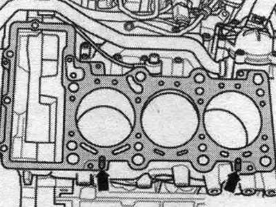
The fixing bolt "T40069" must be screwed into the crankshaft. Install the cylinder head gasket. Pay attention to the centering pins "arrows" in the cylinder block. Cylinder head gasket installation position: "up" mark or cylinder head part number. Install the cylinder head.
Left cylinder head: Insert bolts "1...7", for which correspondingly move the unloaded moving part "A" of the camshaft. Tighten the bolts in sequence. "1...7" in 3 steps.
Right cylinder head: Insert bolts "8...14" by moving the unloaded moving parts "D" and "E" of the camshaft accordingly. Tighten the bolts in sequence. -8... 14- in 3 steps.
All
Install the control chains on the camshafts. Remove the "T40133" camshaft locking pins and "T40069" retaining bolts. Rotate the crankshaft using the "T40058" adapter in the direction of engine rotation by 1 revolution. The "arrow" notches on the exhaust camshaft should point toward the side of the engine.
Left cylinder head: Move the unloaded moving parts of the camshaft "B" and "C" "in the direction of the arrow" until they stop.
Right cylinder head: Move the unloaded movable part of the camshaft "F" in the "direction of the arrow" until it stops.
All
Turn the crankshaft with the adapter "T40058" in the direction of engine rotation "arrow" by 1 turn. The threaded holes "arrows" in the camshafts must point upwards.
Left cylinder head: Insert bolt "15" and tighten it in 3 steps.
Right cylinder head: Insert bolt "16" and tighten it in 3 steps.
All
Turn the crankshaft with the adapter "T40058" in the direction of engine rotation "arrow" by 1 turn. The recesses "arrows" on the exhaust camshaft must point to the engine side.
Left cylinder head: Move the unloaded movable part of the camshaft "B" in the "direction of the arrow" until it stops.
Right cylinder head: Move the unloaded movable part of the camshaft "F" in the "direction of the arrow" until it stops.
All
Tighten the bolts "arrows": left cylinder head: 3 bolts; right cylinder head: 4 bolts. After repair work, do not tighten the cylinder head bolts. Installation is in reverse order. Install the dipstick guide tube. Install the drive chains on the camshafts. Install the cylinder head cover: left. Install the upper coolant supply pipe. Install the power steering pump. Install the left catalytic converter. Install the right catalytic converter. Install the front muffler. Install the front wall of the water drainage box. Install the high pressure line, fuel delivery hose and lower part of the intake manifold. Install the poly V-belt. Installing the upper coolant pipe. Change the oil. Replace the coolant.
Compression check
Oil temperature at least 30°C. Battery voltage minimum 12.5 V. Remove the rear engine cover — upper arrows —. Unscrew the bolts "arrows". Disconnect the electrical connector of the low coolant level warning sensor "F66" and set aside the coolant expansion tank with the connected hoses "1, 2, 3".
Remove the "arrow" bolts and disconnect the electrical connectors from the coils on the left cylinder head. Gently push the wiring harness downwards.
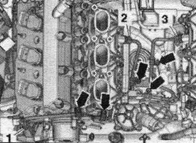
Disconnect electrical connector "3" from the injectors at the rear of the left cylinder head. "Pos. 1, 2, 4" and "arrows" are not taken into account.
Remove the "arrow" air duct.
Release fuel. line "1" and wire "2" to the activated carbon absorber on the air duct. Remove vacuum hose "3" from the air duct connection. Remove the air duct tube by loosening clamp "4" and unlocking the "arrow" clamps.
Disconnect vacuum line "1". Remove air intake housing. filter and, if present, disconnect the electrical connector "2" of the air inlet switching valve "N335" on the reverse side.
Remove the arrow bolts and disconnect the electrical connectors from the coils on the right cylinder head. Push the wiring harness aside.
Disconnect electrical connector "3" from the injectors at the rear of the right cylinder head. "Pos. 1, 2, 4" and "arrows" are not taken into account.
Remove the coils using the T40039 puller. Remove the spark plugs using the 3122 B spark plug wrench. Check the compression pressure using the VAG 1763 compression gauge.
The second mechanic should depress the gas pedal and leave the starter running until the pressure on the compression gauge stops increasing.
| Compression | In case of excess pressure |
| New | 10,0...14,0 |
| Wear tolerance limit | 9,0 |
| Maximum difference between cylinders | 3,0 |
Assembly
Installation in reverse order. Secure all hose connections with hose clamps of the appropriate standard. Install spark plugs. Install the air casing. filter. Since the plug connectors were removed while the engine was running, an error was stored in the engine control unit: perform the "Create Readiness Code" function in the "Guided Functions" mode.