
Table of contents: Cooling system ↓ Hose connection diagram ↓
Cooling system
Caution! Risk of burns from hot steam and hot coolant. When the engine is warm, the cooling system is under excess pressure. To relieve excess pressure, place the expansion cap over the expansion tank. coolant reservoir with a rag and carefully open it. Secure all hose connections with hose clamps of the appropriate standard. Arrows applied to the ends of the tubes and hoses of the system. cooling, must be located opposite each other.
Hose connection diagram
Cars without independent heater
The arrows show the direction of coolant flow.
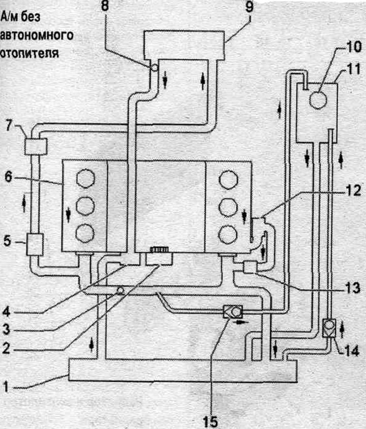
1. Radiator: after replacement, drain the old coolant and fill it with new coolant.
2. Water pump.
3. Coolant temperature sensor "G62".
4. Thermostat.
5. Coolant circulation pump "V50": controlled by the circulation pump relay "J160".
6. Cylinder head to cylinder block: after replacement, drain the old coolant and fill it with new coolant.
7. Coolant shut-off valve: controlled via the Climatronic coolant shut-off valve "N422"; the Climatronic coolant shut-off valve "N422" is controlled by the Climatronic control unit "J255".
8. Ventilation hole.
9. Heater heat exchanger: after replacement, drain the old coolant and fill it with new coolant.
10. Expansion cover. tank.
11. Expansion tank.
12. Oil radiator: after replacement, drain the old coolant and fill it with new coolant.
13. Coolant recovery pump "V51": only for vehicles intended for use in hot countries.
14/15. Check valve.
Car with independent heater
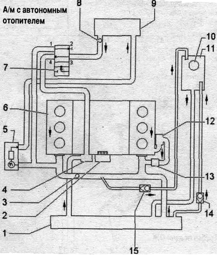
1. Radiator: after replacement, drain the old coolant and fill it with new coolant.
2. Coolant pump.
3. Coolant temperature sensor "G62".
4. Thermostat.
5. Autonomous heater: with circulation pump "V55".
6. Cylinder head to cylinder block: after replacement, drain the old coolant and fill it with new coolant.
7. Climatronic coolant shut-off valve "N422": controlled via the Climatronic control unit "J255".
8. Ventilation hole.
9. Heater heat exchanger: after replacement, drain the old coolant and fill it with new coolant.
10. Expansion cover. tank.
11. Expansion tank.
12. Oil cooler: after replacement, drain the old coolant and fill it with new coolant.
13. Pump for the after-run coolant circulation system -V51-: only for vehicles intended for use in hot countries.
14/15. Check valve.
Cooling system pump, thermostat, fittings
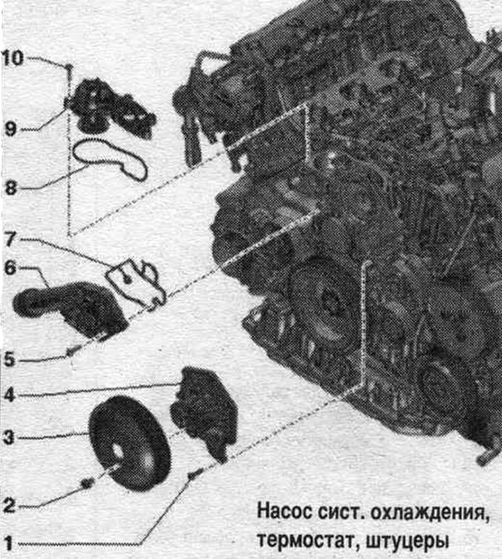
1. Bolt: 9 Nm.
2. Bolt: 20 Nm.
3. Belt drive pulley for water pump.
4. Water pump: with gasket.
5. Bolt: 9 Nm.
6. Connecting pipe of the system hose. cooling.
7/8. Gasket: replace.
9. Thermostat.
10. Bolt: 9 Nm.
Coolant supply pipes
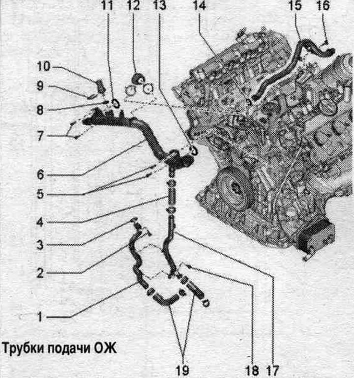
1. Coolant supply pipe, rear: remove and install together with "pos. 17".
2. Bolt: 9 Nm.
3. O-ring: Replace.
4. Connecting hose.
5. Bolts: 9 Nm.
6. Coolant supply pipe, front.
7. Bolts: 9 Nm.
8. Sealing ring: replace.
9. Retainer.
10. Coolant temperature sensor "G62".
11. Sealing cuff: replace.
12. Cooling system hose.
13. Sealing ring: replace.
14. O-ring: Replace.
15. Upper coolant supply pipe.
16. Bolt: 9 Nm.
17. Coolant supply pipe, rear: remove and install together with "pos. 1".
18. Bolt: 9 Nm.
19. Water hoses.
Radiator and radiator fan
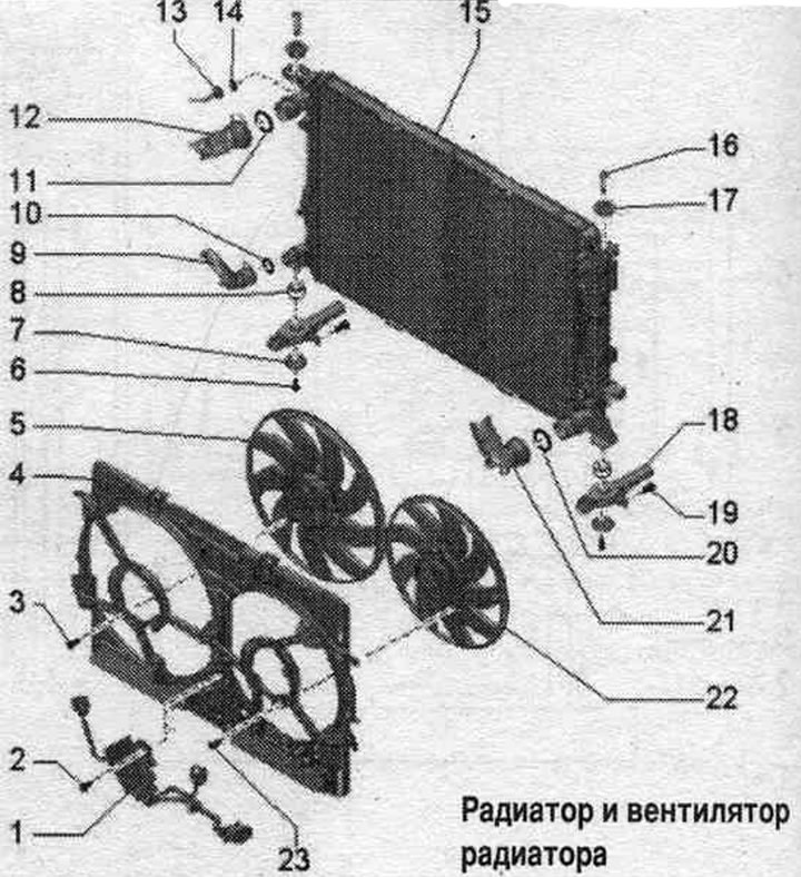
1. Radiator fan control unit "J293": depending on the version, separate or connected to the radiator fan "V7".
2. Bolt: 4.5 Nm.
3. Bolt: 5 Nm.
4. Fan frame.
5. Radiator fan "V7": depending on the version, separate or connected to the radiator fan control unit "J293".
6. Bolt: 3.5 Nm.
7. Lining.
8. Rubber support: for radiator.
9. Cooling system hose: to remove, press the clamp, connect to the radiator.
10/11. Sealing ring: replace.
12. Cooling system hose: to remove, press the clamp, connect to the radiator.
13. Cooling system hose: to expansion tank.
14. Sealing ring: replace.
15. Radiator: after replacement, drain the old coolant and fill it with new coolant.
16. Lock bolt: Unlock with a screwdriver and remove.
17. Rubber buffer.
18. Radiator console.
19. Bolt.
20. Sealing ring: replace.
21. Cooling system hose: to remove, press the clamp, connect to the radiator.
22. Radiator fan 2 "V177": except for 400W fan control; depending on the design, it is separate or connected to the radiator fan control unit.
23. Bolt: 5 Nm.
Connecting the coolant hose with nipple connectors
Remove the old seal. ring "2" in coolant hose "3". Moisten the new seal. coolant ring and insert it into the coolant hose. Push the coolant hose onto the coolant pipe "1" until it clicks into place. Press add. hose and check that it is properly secured with the clamp and final pull.