
Table of contents: Ignition system ↓ Removal and installation coils ↓ Removal and installation knock… ↓ Removal and installation the Hall… ↓
Verification data
| Idle speed | Not regulated |
| Ignition timing | Not adjustable, installed in the control unit |
| Ignition system | Ignition system with 8 separately located ignition coils (with integrated output stages), which are placed directly on the spark plugs through the spark plug cap |
| Cylinder firing order | 1-5-3-6-2-4 |
Ignition system

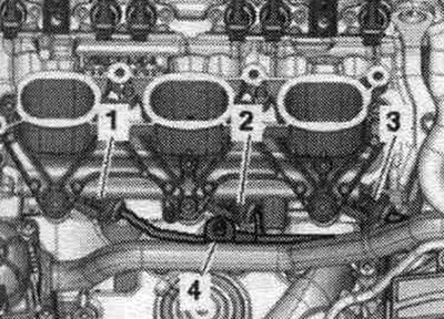
1. Coil connector: 4-pin.
2. Bolt: 10 Nm.
3. 3-pin plug connector.
4. Hall sensor. Hall sensor "G40" (cylinder bank 1). Hall Sensor 3 "G300" (cylinder bank 1). Hall sensor 2 "G163" (cylinder bank 2). Hall sensor 4 "G301" (cylinder bank 2).
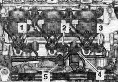
5. Sealing ring: if damaged, replace and lubricate with clean oil.
6. Bolt: 20 Nm; the tightening torque affects the operation of the knock sensor.
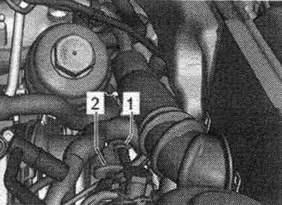
7. Knock sensors: the mating surfaces of the knock sensor and the cylinder block must be free of corrosion, contamination and grease; knock sensor 1 "G61" (cylinder bank 1), knock sensor 2 "G66" (cylinder bank 1).
8. Spark plug: remove and install using the spark plug wrench "3122 B"; 30 Nm.
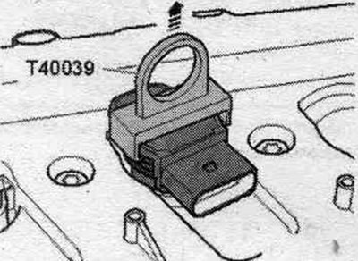
9. Coil. Coil 1 with output stage "N70". Coil 2 with output stage "N127". Coil 3 with output stage "N291". Coil 4 with output stage "N292". Coil 5 with output stage "N323". Coil 6 with output stage "N324"; to remove, use the "T40039" puller.
Removal and installation coils
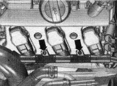
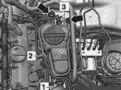
Removing coils from cylinder bank 1: Only with coil cyl. 1 remove the lower part of the air. filter. For cyl. coils. 2 and 3 remove the air duct hose (open clamp "3" and clamps "arrows"). Unscrew the coil wiring harness bolts. Unlock the connectors and remove them from the coils simultaneously.
Remove the coils from the spark plug sockets using the T40039 puller.
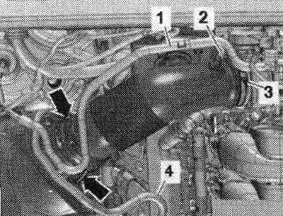
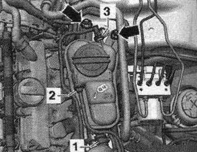
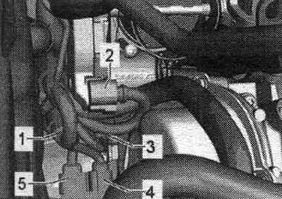
Removing the coils from cylinder bank 2: Unscrew the coolant expansion tank "arrows". Disconnect the plug connector of the low coolant level indicator sensor "F66" from the bottom of the expansion tank. tank and put the expansion tank with the connected coolant hoses "1, 2" and "3" aside.
Remove the "arrow" bolts. Using the "T40039" puller, pull the ignition coil approximately 30 mm out of the coil socket.
Unlock the connectors and remove them from the coils simultaneously.
Installation
Insert the coils into the spark plug sockets without force. Align the coils with the connectors and simultaneously place all connectors on the coils. Use your hand to press the coils evenly onto the spark plugs (do not use impact instruments!). Installation in reverse order. Coil wire harness to cylinder head: 5 Nm.
Removal and installation knock sensors
Electrical connectors
1. To the injectors of cylinder bank 1. 2. Throttle control unit "J338". 3. Knock sensor 1 "G61". 4. Lambda probe "G39". 5. Lambda probe after catalytic converter "G130".
1. Knock sensor 2 "G66". 2. Injectors of cylinder bank 2 and fuel pressure sensor "G247".
Remove the knock sensor for the right bank of cylinders
4. Knock sensor 1 "G61". To access the knock sensor bolt 1 "G61" "4", remove the injector 2. Remove the intake manifold. Remove the lower right part of the intake manifold from the fuel. ramp.
Remove the knock sensor from the left bank of cylinders
5. Knock sensor 2 "G66". To access the knock sensor 2 "G66" bolt "5", remove injector 5. Remove the intake manifold. Install the appropriate lower part of the intake manifold with fuel. ramp.
Installation
Reinstall the removed knock sensor. Tightening torque affects the operation of the knock sensor. Install the appropriate lower part of the intake manifold with fuel. ramp. Install the intake manifold in place.
Removal and installation the Hall sensor
Disconnect the connector from the corresponding Hall sensor. To remove Hall sensor 3 "G300" from cylinder bank 1, it is necessary to remove the air intake manifold housing. filter. To remove the Hall sensor 4 "G301" from cylinder bank 2, it is necessary to remove the expansion tank. Disconnect the plug connector of the low coolant level indicator sensor "F66" from the bottom on the expansion tank. tank and put the expansion tank with the connected coolant hoses "1, 2" and "3" aside.
Installation
Replace the sealing rings and lubricate them with clean oil. Gently press the Hall sensor in by hand. Tighten the Hall sensor bolts and reconnect the connector. Installation in reverse order.
(The original text is available on the website: audimanual.ru)