
Table of contents: Overview of installation locations ↓ Upper part of the intake manifold ↓ Intake manifold with fuel. ramp ↓ Removal and installation the upper… ↓ High pressure pump ↓
Technical data
| Verification data | Engine 3.2 l/4V/195 kW |
| Idle speed. Not adjustable, achieved by stabilizing idle speed | 650...750 rpm (1) |
| Fuel pressure at the outlet of the high pressure pump | 40...110 bar excess pressure |
| Fuel pressure before the high pressure pump | 3.0...6 bar excess pressure |
(1) Depending on the requirements of the engine control unit.
Overview of installation locations
Right side of the motorcycle. compartment
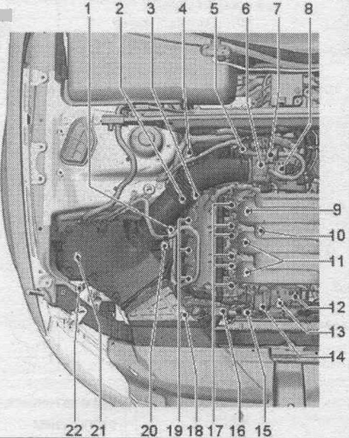
1. Lambda probe "G39": 55 Nm.
2. Valve 1 for adjusting the exhaust valve timing phases "N318": replace the seal. ring; 2.5 Nm.
3. Valve 1 for adjusting the timing phases "N205": replace the seal. ring; 2.5 Nm.
4. Lambda probe after catalytic converter "G130": 55 Nm.
5. Plug connector: injectors of 1st row of cylinders; throttle control unit "J338"; for knock sensor 1 "G61"; for lambda probe "G39"; lambda probe after the "G130" catalytic converter.
6. Throttle control unit "J338": with electric throttle drive "G186", angle sensor 1 of electric throttle drive "G187" and angle sensor 2 of electric throttle drive "G188"; after replacing the throttle module, perform adaptation in the "Guided functions" mode in the "Throttle module adaptation" section.
7. Electromagnetic valve 1 of the absorber with activated carbon "N80".
8. Intake air temperature sensor "G42"/intake manifold pressure sensor "G71".
9. Injector of cylinder bank 1. Injector cyl. 3 "N32".
10. Knock sensor 1 "G61".
11. Injectors, cylinder bank 1. Injector cyl. 1 "N30". Cyl. injector. 2 "N31".
12. Variable geometry intake manifold position sensor "G513".
13. Intake manifold sequential switching valve "N156".
14. Actuating element for changing the geometry of the intake manifold: vacuum reservoir.
15. Coolant temperature sensor "G62".
16. Hall sensor "G40": replace the seal. ring; 9 Nm.
17. Actuating elements of the valve timing control: Actuating element 1 of the valve timing control "F366". Actuating element 2 of the valve timing control "F367". Actuating element 3 of the valve timing control "F368". Actuating element 4 of the valve timing control "F369". Actuating element 5 of the valve timing control "F370". Actuating element 6 of the valve timing control "F371".
18. High-pressure pump: with low-pressure fuel pressure sensor "G410" and fuel metering valve "N290".
19. Ignition coils for cylinder bank 1: Coil 1 with final stage "N70". Coil 2 with final stage "N127". Coil 3 with final stage "N291".
20. Hall sensor 3 "G300": replace seal. ring; 9 Nm.
21. Secondary air pump electric motor "V101": not installed on all vehicles (only with Euro 5).
22. Intake air changeover valve "N335": not installed on all vehicles.
Left side of the motorcycle. compartment
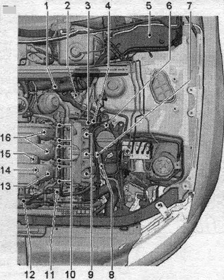
1. Left connector bracket: for knock sensor 2 "G66", injectors of 2 cylinder rows, for fuel pressure sensor "G247".
2. Lambda probe 2 after catalytic converter "G131": 55 Nm.
3. Valve 2 for adjusting the timing phases "N208": replace the seal. ring; 2.5 Nm.
4. Valve 2 for adjusting the valve timing of the exhaust valves "N319": replace the seal. ring; 2.5 Nm.
5. Engine control unit "J623".
6. Lambda probe 2 "G108": 55 Nm.
7. Hall sensor 4 "G301": replace seal. ring; 9 Nm.
8. Oil pressure regulating valve "N428".
9. Ignition coils of cylinder bank 2: Coil 4 with output stage "N292". Coil 5 with output stage "N323". Coil 6 with output stage "N324".
10. Actuating elements of valve timing control: Actuating element 7 of valve timing control "F372". Actuating element 8 of valve timing control "F373". Actuating element 9 of valve timing control "F374". Actuating element 10 of valve timing control "F375". Actuating element 11 of valve timing control "F376". Actuating element 12 of valve timing control "F377".
11. Hall sensor 2 "G163": replace seal. ring; 9 Nm.
12. Variable geometry intake manifold position sensor "G513".
13. Injector of cylinder bank 2. Injector cyl. 4 "N33".
14. Fuel pressure sensor "G247".
15. Knock sensor 2 "G66".
16. Injectors, cylinder bank 2. Injector cyl. 5 "N83". Cyl. injector. 6 "N84".
A. Engine speed sensor "G28": 9 Nm.
B. Fuel control unit. pump "J538".
C. Accelerator pedal position sensor "G79"/Accelerator pedal position sensor 2 "G185": in the footwell on the accelerator pedal (both sensors are located in the same housing).
D. Brake light switch "P"/brake pedal sensor "F47": in the footwell on the accelerator pedal.
E. Clutch pedal position sensor "G476": installed only on vehicles with manual transmission.
F. Oil pressure sensor "F22".
G. Oil pressure sensor for low pressure "F378".
Installation location of the engine control unit "J623"
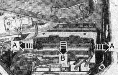
In the left switching unit of the motor. compartment.
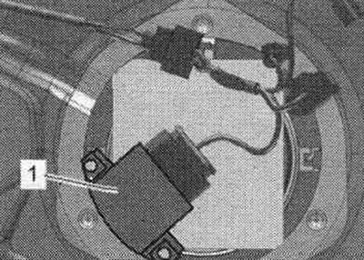
Fuel control unit. pump "J538" "1"
Relay and fuse box in the junction box in the left water drain box
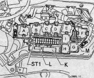
A. Engine electronics power supply relay "J757". B. Starter relay "J53" (base color: black/purple). B. Starter relay 2 "J695" (base color: black/blue). C. Secondary air pump relay "J299". D. Motronic power supply relay "J271". E. Coolant bleeding relay after switching off. engine "J151" (base color: brown/blue). E. Brake booster relay "J569" (base color: brown/lilac).
Accelerator pedal position sensor "G79" and accelerator pedal position sensor 2 "G185"
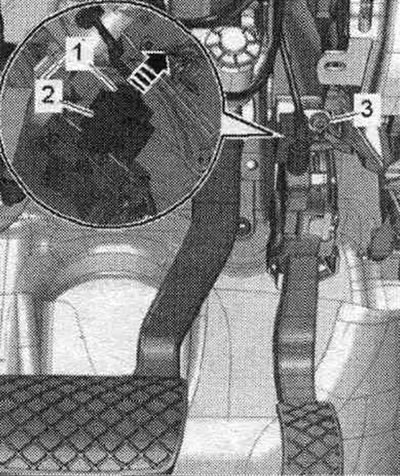
2. Plug connector
Clutch pedal position sensor "G476" "2"
Built-in functions: clutch pedal position sensor for engine starting "F194" and clutch pedal switch "F36".
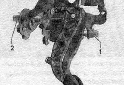
1. Brake light sensor "F" and foot brake pedal position sensor "F47"
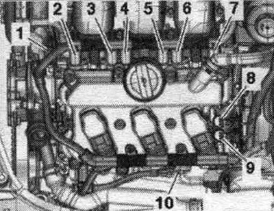
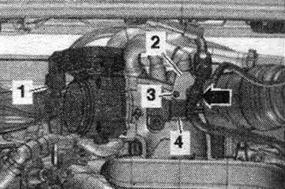
Installation location on the right bank of cylinders 1
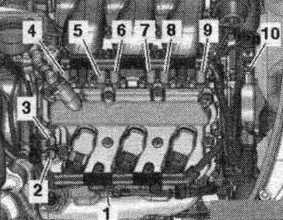
1. Hall sensor 3 "G300". 2. Valve 1 of the exhaust valve timing control system "N318". 3. Valve 1 of the valve timing control system "N205" (Timing phase regulator B cylinder 1). 4. Executive element 2 of the timing phase adjustment system "F371" (Timing phase regulator B cylinder 3). 5. Executive element 5 of the timing phase adjustment system "F370" (Timing phase regulator A cylinder 3). 6. Executive element 4 of the timing phase adjustment system "F369" (Timing phase regulator B cylinder 2). 7. Executive element 3 of the timing phase adjustment system "F368" (Timing phase regulator A cylinder 2). 8. Executive element 2 of the timing phase adjustment system "F367" (Timing phase regulator B cylinder 1). 9. Executive element 1 of the timing phase adjustment system "F366" (Timing phase regulator A cylinder 1). 10. Hall sensor "G40".
Mounting locations on the left bank of cylinders 2
1. Hall sensor 2 "G163". 2. Actuator element 7 of the timing phase adjustment system "F372" (Timing phase regulator A cylinder 4). 3. Executive element 8 of the timing phase adjustment system "F373" (Timing phase regulator B cylinder 4). 4. Executive element 9 of the timing phase adjustment system "F374" (Timing phase regulator A cylinder 5). 5. Executive element 10 of the timing phase adjustment system "F375" (Timing phase regulator B cylinder 5). 6. Executive element 11 of the timing phase adjustment system "F376" (Timing phase regulator A cylinder 6). 7. Executive element 12 of the timing phase adjustment system "F377" (Timing phase regulator B cylinder 6). 8. Valve 2 for adjusting the timing phases "N208". 9. Valve 2 for adjusting the timing phases of the exhaust valves "N319". 10. Hall sensor 4 "G301".
Installation locations: view from inside from the right bank of cylinders 1
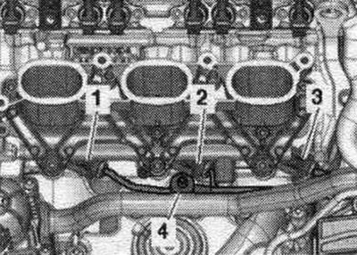
1. Injector cyl. 1 "N30". 2. Cyl. injector. 2 "N31". 3. Cyl. injector. 3 "N32". 4. Knock sensor 1 "G61".
Installation locations: view from inside from left cylinder bank 2
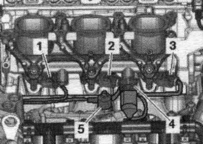
1. Injector cyl. 6 "N84". 2. Cyl. injector. 5 "N83". 3. Cyl. injector. 4 "N33". 4. Fuel pressure sensor "G247". 5. Knock sensor 2 "G66".
Oil pressure sensor "F22" "arrow"
Low pressure oil pressure sensor "F378"
Oil pressure regulating valve "N428"
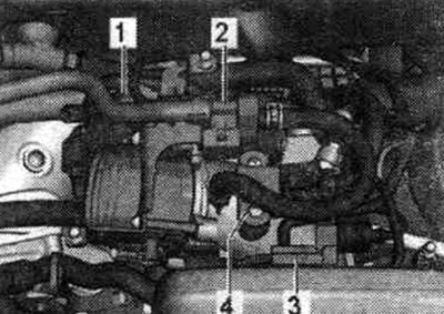
Installation location: front, near the engine
1. Coolant temperature sensor "G62". 2. Intake manifold sequential changeover valve "N156". 3. Variable geometry intake manifold position sensor "G513".
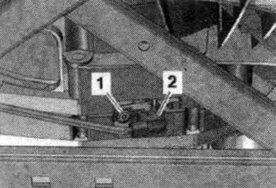
Installation locations on the fuel injection pump
1. Low-pressure fuel pressure sensor "G410". 2. Fuel metering valve "N290".
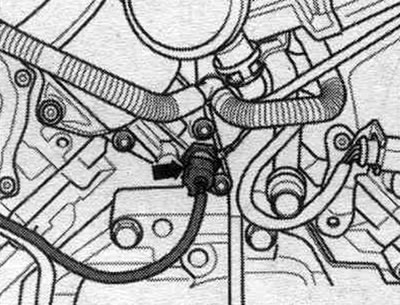
Installation location of the engine speed sensor "G28"
Screwed to the gearbox from below.
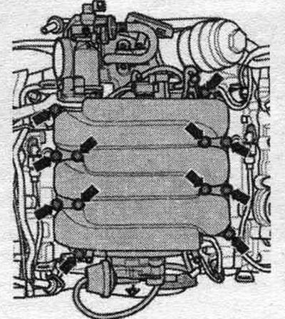
Electrical connectors
1. Injectors, cylinder bank 1. 2. Throttle control unit "J338". 3. Knock sensor 1 "G61". 4. Lambda probe "G39". 5. Lambda probe after catalytic converter "G130".
Electrical connectors
1. Knock sensor 2 "G66". 2. Injectors of cylinder bank 2 and fuel pressure sensor "G247".
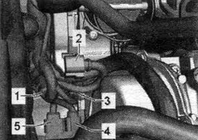
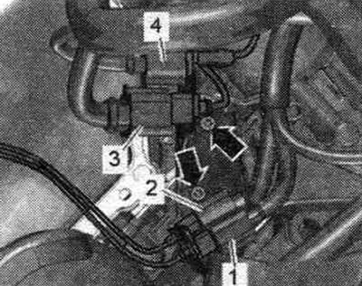
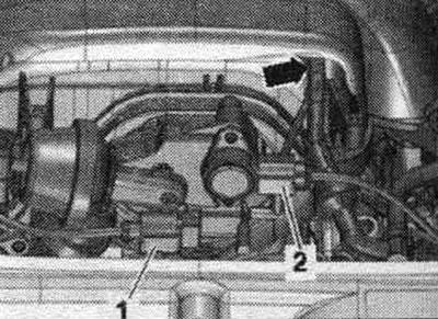
Installation location: rear, near the intake manifold
 1. Throttle control unit "J338". 2. Solenoid valve 1 of the activated carbon canister "N80". 3. Coolant shut-off valve Gimatronic "N422" (on vehicles with an independent heater, a shut-off valve is not installed). 4. Intake air temperature sensor "O42"/intake manifold pressure sensor "G71".
Electrical connectors for lambda probes, 2 cylinder banks
1. Lambda probe 2 after catalytic converter "G131". 2. Lambda probe 2 "G108". 3. Injectors of cylinder bank 2 and fuel pressure sensor "G247". 4. Knock sensor 2 "G66".
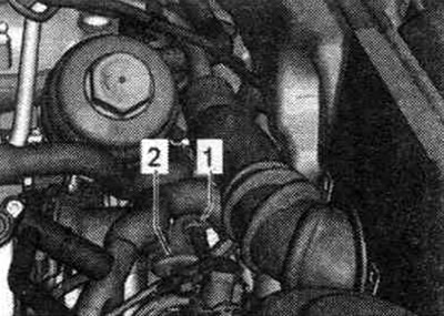
Location of lambda probes for the 1st cylinder bank (right)
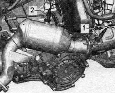
1. Lambda probe "G39". 2. Lambda probe after catalytic converter "G130".
Location of lambda probes for the 2nd row of cylinders (left)
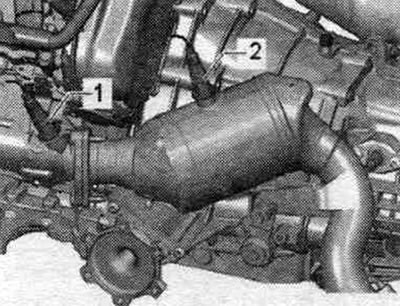
1. Lambda probe 2 "G108". 2. Lambda probe 2 after catalytic converter "G131".
Upper part of the intake manifold
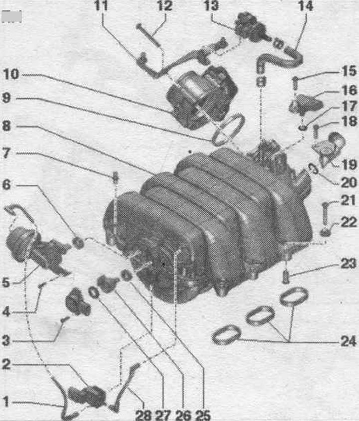
1. Vacuum hose.
2. Intake manifold sequential switching valve "N156".
3/4. Bolt: 2.5 Nm.
5. Intake manifold geometry switching regulator: spare part together with "pos. 26".
6. Lip seal: replace if damaged. To replace, lift with a screwdriver and press by hand.
7. Ball pin: 2.5 Nm.
8. Upper part of the intake manifold.
9. Lip seal: replace.
10. Throttle control unit "J338".
11. Bracket.
12. Bolt: 6 Nm.
13. Electromagnetic valve 1 of the activated carbon absorber "N80".
14. Hose.
15. Bolt: 3 Nm.
16. Intake air temperature sensor "G42"/intake manifold pressure sensor "G71".
17. Sealing ring: replace.
18. Bolt: 2.5 Nm.
19. Engine crankcase ventilation hose.
20. Sealing ring: replace.
21. Bolt: 8 Nm.
22. Washer.
23. Bushing.
24. Gaskets: replace.
25. Lip seal: replace if damaged. To replace, lift with a screwdriver and press by hand.
26. Lever with toothed segment: intake manifold geometry switching flaps: spare part together with "pos. 5".
27. Lip seal: replace if damaged. To replace, lift with a screwdriver and press by hand.
28. Vacuum hose.
Installation location of the toothed segment of the intake manifold geometry switching valve
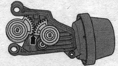
The lower edges of the toothed segment must be level with each other "arrow".
Intake manifold with fuel. ramp
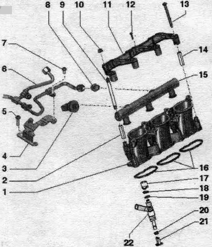
1. Lower part of the intake manifold.
2. Bushing.
3. Fuel pressure sensor "G247": 20 Nm.
4. Bracket.
5. Bolt: 9 Nm.
6. High pressure line: relieve fuel pressure in the high pressure circuit, do not change the bent shape; do not bend the fuel holder under any circumstances. highways; if the holder was bent or damaged. if the line needs to be replaced, then the holder must also be replaced.
7. Bolt: 9 Nm.
8. Threaded nipple: 40 Nm.
9. Mounting pin.
10. Nut: 9 Nm.
11. Fuel locking bracket. ramps.
12. Bolt: 2.5 Nm.
13. Bolt: 9 Nm.
14. Bushing.
15. Fuel rail.
16. Gaskets: replace.
17. Support ring: check for proper fit; by means of a fuel spacer ring. the ramp creates a force that holds the injector in the cylinder head.
18. Sealing ring: replace, lubricate with clean oil.
19. Spacer ring: replace if damaged.
20. Combustion chamber sealing ring.
21. Radial compensator: replace if damaged; clip to the support ring "pos. 17".
22. Nozzle.
Installation of a high-pressure line
Tighten the high pressure line union nut by hand. Ensure that the high pressure line is installed without tension. For tightening the high pressure fuel line. on the ramp, use the torque wrench "VAG 1331" with an open-end ring spanner for 17 "VAG1331/2".
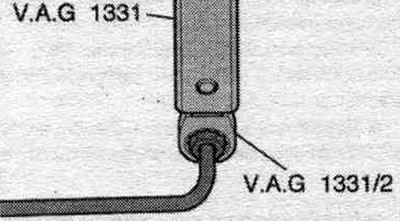
Tightening torque: high-pressure line union nut, 27 Nm.
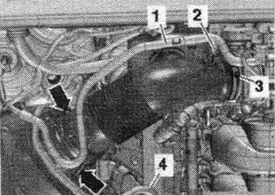
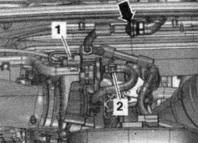
Removal and installation the upper part of the intake manifold
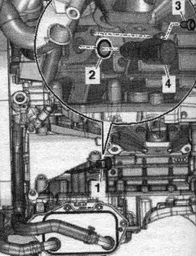
During installation, all cable ties should be placed in their original locations. Remove the front and rear engine covers. Release hose line "1" to the activated carbon absorber. Disconnect vacuum hose "2" from the air duct hose connection. Remove the air duct hose by loosening the hose clamp "3" and opening the clamps "arrows." Ignore "Pos. 4.".
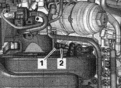
Disconnect the plug connector "1" of the el. magnetic valve 1 of the activated carbon canister "N80" and remove the vacuum hose "2". Release the el. magnetic valve 1 of the activated carbon absorber "N80" from the bracket and together with the connected hose put aside. Ignore the arrow.
Disconnect the electrical connector plugs.
1. Sequential intake manifold changeover valve "N156". 2. Variable geometry intake manifold position sensor "G513".
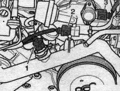
Remove the vacuum hose "arrow". Disconnect the electrical connectors.
1. Throttle control unit "J338". 4. Intake air temperature sensor "C42"/intake manifold pressure sensor "G71".
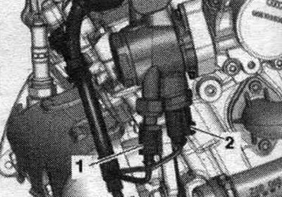
Release the vacuum hose "arrow". Disconnect the electrical wiring. Loosen bolt "3". Press locking tab "2" upward and remove the crankcase ventilation hose from the intake manifold. Unscrew the "arrow" bolts and remove the upper part of the intake manifold. Plug the intake channels of the cylinder heads with a clean rag.
Installation
Installation in reverse order. Replace gaskets and seals. o-rings. During installation, all cable ties should be placed in their original locations. To secure all hose connections, use clamps of the appropriate series.
High pressure pump
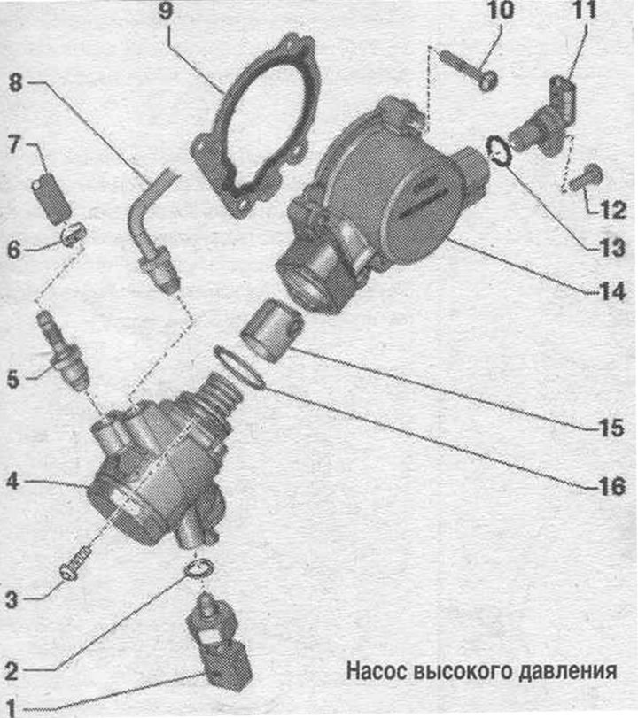
1. Low pressure fuel pressure sensor "G410": 15 Nm.
2. Lip seal: replace.
3. Bolt: tighten crosswise to 5 Nm, final torque 20 Nm; avoid distortion of the high pressure pump.
4. High pressure pump: with fuel metering valve "N290"; for loosening and tightening fuel. hold the fittings of the main lines; before installing fuel. first tighten the fuel lines. highways; do not disassemble.
5. Threaded fitting: 27 Nm.
6. Hose clamp: replace; select a clamp of the corresponding series.
7. Fuel pre-supply hose: low pressure circuit.
8. High-pressure fuel line: relieve fuel pressure in the high-pressure circuit; to loosen and tighten the union nuts, hold the high-pressure pump nipples; before installation, tighten the nipple on the high pressure pump.
9. Gasket: replace.
10. Bolt: 9 Nm.
11. Hall sensor "G40".
12. Bolt: 9 Nm.
13. Sealing ring: replace; before installation, wet with clean oil.
14. Body.
15. Roller tappet: moisten with clean oil before installation.
16. Sealing ring: replace; before installation, wet with clean oil.
Tightening torque of the high-pressure line protective screen
Tighten the bolts "arrow" of the protective screen "1".
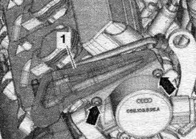
Tightening torque: 9 Nm.
Installation of a high-pressure line
Tighten the high pressure line union nut by hand. Ensure that the high pressure line is installed without tension. To tighten the high-pressure line on the high-pressure pump, use the torque wrench "VAG 1331" with a ratchet "VAG 1331/1" and a 14 mm "3150" socket wrench.
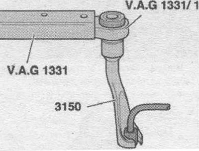
Tightening torque: union nut for high pressure line, 25 Nm.
[This article was copied from an online resource AUDIMANUAL.ru]