



Fuel and exhaust system of car Audi A4 B7

Fuel and exhaust systems — specifications
Fuel system and engine management type Petrol engines 1.8 l (code BFB), 2.0 l (code ALT) and 3.0 l (code BBJ). Distributed sequential injection, controlled by...
Fuel system and engine management type Petrol engines 1.8 l (code BFB), 2.0 l (code ALT) and 3.0 l (code BBJ). Distributed sequential injection, controlled by...
Power supply system: general information and safety precautions
The fuel system includes a saddle-shaped fuel tank installed in the rear of the vehicle and a carbon fuel vapor absorber (only on petrol models), fuel lines,...
The fuel system includes a saddle-shaped fuel tank installed in the rear of the vehicle and a carbon fuel vapor absorber (only on petrol models), fuel lines,...

Operating principles of the engine management system
Note: The following describes the operating principle of a typical gasoline engine control system. The features of a diesel engine control system are described...
Note: The following describes the operating principle of a typical gasoline engine control system. The features of a diesel engine control system are described...

Removal and installation the air cleaner, replacing its filter element
Note: Replacing the air cleaner filter element is described in Chapter 1 . 1. The installation details of the air cleaner for 2.0 TFSI engines are shown in the...
Note: Replacing the air cleaner filter element is described in Chapter 1 . 1. The installation details of the air cleaner for 2.0 TFSI engines are shown in the...

Removal and installation the intake manifold
2.0 TFSI engines Note: After removing or replacing the intake manifold, the intake manifold flap position sensor must be initialized using diagnostic...
2.0 TFSI engines Note: After removing or replacing the intake manifold, the intake manifold flap position sensor must be initialized using diagnostic...

Removal and installation of fuel distribution line and injectors
2.0 TFSI engines 1. The installation details of the fuel distribution line and injectors are shown in the illustration. 5.1. Fuel distribution line and...
2.0 TFSI engines 1. The installation details of the fuel distribution line and injectors are shown in the illustration. 5.1. Fuel distribution line and...

Removal and installation the intercooler
2.0 TFSI engines 1. The intercooler installation details are shown in the illustration. 6.1. Intercooler installation details 1. Intercooler air duct; 2. Air...
2.0 TFSI engines 1. The intercooler installation details are shown in the illustration. 6.1. Intercooler installation details 1. Intercooler air duct; 2. Air...

Removal and installation a turbocharger
2.0 TFSI engines 1. Turbocharger installation details are shown in the illustrations. 7.1a. Turbocharger Installation Details, Part 1 of 4 1. PCV hose; 2. ACF...
2.0 TFSI engines 1. Turbocharger installation details are shown in the illustrations. 7.1a. Turbocharger Installation Details, Part 1 of 4 1. PCV hose; 2. ACF...

Removal and installation of fuel injection pump
2.0 TFSI engines 1. The details of the fuel injection pump installation are shown in the illustrations. 8.1. Fuel injection pump installation details 1....
2.0 TFSI engines 1. The details of the fuel injection pump installation are shown in the illustrations. 8.1. Fuel injection pump installation details 1....

Removal and installation of pump-injectors
Diesel engines 1.9 and 2.0 SOHC 1. Remove the cylinder head cover ( see Chapter 2 ). 2. Turn the crankshaft so that both cams of the corresponding unit...
Diesel engines 1.9 and 2.0 SOHC 1. Remove the cylinder head cover ( see Chapter 2 ). 2. Turn the crankshaft so that both cams of the corresponding unit...
Removal and installation the gas pedal
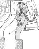
1. Remove the driver's storage compartment ( see Chapter 11 ). 2. Disconnect the connector (2 in the illustration), unscrew the bolts (1 and 3) and remove the...
1. Remove the driver's storage compartment ( see Chapter 11 ). 2. Disconnect the connector (2 in the illustration), unscrew the bolts (1 and 3) and remove the...

Removal and installation the fuel tank
1. The fuel tank installation details for gasoline models are shown in the illustrations. For diesel models, the difference is the absence of EVAP lines. The...
1. The fuel tank installation details for gasoline models are shown in the illustrations. For diesel models, the difference is the absence of EVAP lines. The...

Removal and installation the fuel supply module
1. The fuel delivery module installation details are shown in the illustrations. The removal and installation procedure is given using the example of...
1. The fuel delivery module installation details are shown in the illustrations. The removal and installation procedure is given using the example of...

Removal and installation the EVAP canister (petrol models)
1. Remove the right front wheel and the right front wheel arch liner ( see Chapter 11 ). 2. Remove the cover from the front right side of the underbody (see...
1. Remove the right front wheel and the right front wheel arch liner ( see Chapter 11 ). 2. Remove the cover from the front right side of the underbody (see...

Replacing the fuel level sensor
1. Remove the fuel delivery module ( see Section 12 ). 2. Use a screwdriver to press the fasteners (arrows in the illustration) and lift the sensor up. 14.2....
1. Remove the fuel delivery module ( see Section 12 ). 2. Use a screwdriver to press the fasteners (arrows in the illustration) and lift the sensor up. 14.2....
Exhaust and Emission Control Systems — General Information
Exhaust system The exhaust gas (EG) exhaust system consists of exhaust manifolds with catalytic converters and a particulate filter (DPF, only on some diesel...
Exhaust system The exhaust gas (EG) exhaust system consists of exhaust manifolds with catalytic converters and a particulate filter (DPF, only on some diesel...

Removal and installation the exhaust manifold
Note: The exhaust manifold on 2.0 TFSI petrol models is a single, non-separable unit with the turbocharger and its vacuum unit. A description of the design,...
Note: The exhaust manifold on 2.0 TFSI petrol models is a single, non-separable unit with the turbocharger and its vacuum unit. A description of the design,...

Removal and installation of exhaust system components
Note: To remove the exhaust system assembly, please have an assistant assist you due to its considerable weight. Wait until the exhaust system has cooled down...
Note: To remove the exhaust system assembly, please have an assistant assist you due to its considerable weight. Wait until the exhaust system has cooled down...

Removal and installation of the radiator and vacuum block of the EGR system
1. The installation details of the EGR system components using 2.0 DOHC diesel engines as an example are shown in the illustration. 18.1. EGR system...
1. The installation details of the EGR system components using 2.0 DOHC diesel engines as an example are shown in the illustration. 18.1. EGR system...
This section is available on russian, bulgarian, belarusian, ukrainian, serbian, croatian, romanian, polish, slovak, hungarian
Similar sections of other Audi car models:
Power unit: Fuel and exhaust systems Audi 80 B3 (1986-1991, petrol)
Power unit: Fuel system (diesel) Audi 100 C3 (1982-1990)
Power unit: Supply system Audi A3 Type 8L (1996-2003)
Power unit: Fuel system (diesel) Audi A6 C5 Allroad (1999-2005)
Power unit: Fuel system (diesel) Audi A8 D2 (1994-2002)
Power unit: Fuel and exhaust system Audi Q7 Typ 4L (2005-2015, diesel)
Engine 1.4 l (diesel): Supply system Audi A2 (1999-2005)
Power unit: Fuel and exhaust systems Audi 80 B3 (1986-1991, petrol)
Power unit: Fuel system (diesel) Audi 100 C3 (1982-1990)
Power unit: Supply system Audi A3 Type 8L (1996-2003)
Power unit: Fuel system (diesel) Audi A6 C5 Allroad (1999-2005)
Power unit: Fuel system (diesel) Audi A8 D2 (1994-2002)
Power unit: Fuel and exhaust system Audi Q7 Typ 4L (2005-2015, diesel)
Engine 1.4 l (diesel): Supply system Audi A2 (1999-2005)
Share information:
- General information
- Operating instructions
- Power unit
- Petrol engines 1.8 l
- Petrol engines 1.8/2.0 l
- Petrol engines 3.0 l
- Petrol engines 3.2 l
- Fuel system (petrol)
- Diesel engines 2.0 l (CA*)
- Diesel engines 2.0 l (CJCB)
- Diesel engines 2.7/3.0 l
- Diesel engines 3.0 l
- Fuel system (diesel)
- Transmission
- Manual gearbox 0B1
- Manual gearbox 0B2
- Manual gearbox 0B3
- Manual gearbox 0B4
- Automatic transmission 0B5
- Automatic transmission 0B6
- Automatic transmission 0AW
- All-wheel drive system
- Chassis
- Front suspension
- Rear suspension
- Brake system
- Steering system
- Body
- Exterior
- Interior
- Seats
- Doors, locks and windows
- Security system
- Heating and air conditioning
- Electrical equipment
- Audio system
- Power devices
- Equipment and devices
- Lighting and lamps
- Electrical circuits
- General information
- Introduction to manual
- Troubleshooting
- Operating instructions
- Maintenance
- Power unit
- Petrol engines 2.0 (ALT)
- Petrol engines 2.0 (TFSI)
- Petrol engines 1.8 (MPI)
- Diesel engines
- Cooling system
- Air conditioner
- Fuel and exhaust system
- Ignition system
- Starting and charging
- Transmission
- Clutch
- Manual gearbox
- Automatic gearbox
- Drive shafts
- Chassis
- Brake system
- Front suspension
- Rear suspension
- Steering
- Body
- Exterior
- Interior
- Electrical equipment
- Equipment and devices
- Lighting and signaling
- Windscreen wipers and washers
- Electrical diagrams
- Electrical diagrams (since 2007)
- General information
- Vehicle Description
- User manual
- Maintenance
- Power unit
- Gasoline engine
- Diesel engine
- Lubrication system
- Cooling system
- Supply system
- Injection system
- Exhaust system
- Ignition and control
- Transmission
- Gear box
- Clutch and drive shafts
- Chassis
- Brake system
- Car suspension
- Steering
- Body
- Heating and ventilation
- Exterior (external elements)
- Interior (internal elements)
- Electrical equipment
- Power devices
- Lighting and appliances
- Electrical circuits
- General information
- Introduction to the guide
- Car care
- Power unit
- Engine repair
- Lubrication system
- Cooling system
- Injection and control system
- Ignition system
- Power and exhaust system
- Transmission
- Clutch and drive shafts
- Car gearbox
- Chassis
- Suspension and wheels
- Steering
- Brake system
- Body
- Interior
- Exterior
- Electrical equipment
- Equipment and devices
- Lighting and signaling
- Power devices
- Electrical circuits
- General information
- Introduction to the guide
- Car care
- Maintenance (gasoline)
- Maintenance (diesel)
- Power unit
- Gasoline engines
- Diesel engines
- Engine overhaul
- Cooling system
- Fuel injection (gasoline)
- Fuel system (diesel)
- Exhaust system
- Ignition system
- Transmission
- Clutch
- Mechanical gearbox
- Automatic gearbox
- Drive shafts
- Chassis
- Brake system
- Car suspension
- Steering
- Body
- Exterior
- Interior
- Doors, locks and windows
- Heating and ventilation
- Electrical equipment
- Power devices
- Equipment and devices
- Electrical circuits
- General information
- Vehicle description
- Maintenance
- Power unit
- Engine repair
- Turbocharging
- Exhaust system
- Cooling system
- Ignition system
- Fuel system
- Motronic injection system
- MPI and MPFI injection system
- Transmission
- Clutch
- Gearbox and shafts
- Chassis
- Steering
- Car suspension
- Brake system
- Wheels and tires
- Body
- Heating and ventilation
- Body parts
- Electrical equipment
- Fuses and relays
- Power devices
- Lighting and lamps
- Tools and devices
- Electrical circuits