
Table of contents: Engine 3.2 FSI ↓ Diesel engines 2.0L DOHC ↓
Note: The exhaust manifold on 2.0 TFSI petrol models is a single, non-separable unit with the turbocharger and its vacuum unit. A description of the design, removal and installation of the turbocharger is given in Section 7.
Engine 3.2 FSI
1. The details of the exhaust manifold installation are shown in the illustration. The procedure is described for the left side; on the right side - similarly.
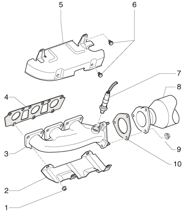
16.1. Exhaust manifold installation details 1. Nut, 25 Nm, subject to replacement; 2. Heat shield bracket; 3. Exhaust manifold; 4. Gasket, subject to replacement; 5. Heat shield; 6. Bolts, 10 Nm; 7. Pre-catalytic lambda probe, 55 Nm; 8. Front exhaust pipe; 9. Nut, 27 Nm, subject to replacement; 10. Gasket, subject to replacement
2. Remove the upper decorative engine cover (see Chapter 2)
3. Loosen the fasteners of the expansion tank of the cooling system and put the tank aside without disconnecting the hoses from it (see Chapter 3).
4. Remove the nut from above (2 in illustration 17.19) fastening the exhaust pipe to the exhaust manifold.
5. Drain the coolant (see Chapter 3) and remove the left front wheel.
6. Remove the bolts (arrows in illustration 17.23) fastenings of the left drive shaft and separate it from the transmission. Unscrew the remaining nuts from under the car (1 and 3 in illustration 17.19) fastening the front exhaust pipe.
7. Loosen the clamps (see illustration 17.25), slide them back and pull the front exhaust pipe away from the exhaust manifold (the exhaust pipe remains on the car).
8. Remove the bolts from underneath (3 and 4 in the illustration) fastenings of the heat shield.
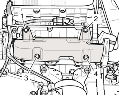
16.8. Fastening the heat shield
9. Remove the front decorative engine cover and disconnect the coolant hoses shown in the illustrations.
16.9a. Coolant hose on the front coolant pipe
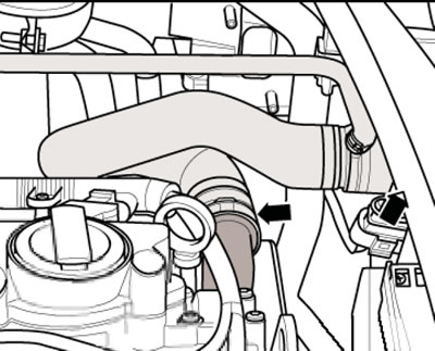
16.9b. Front left coolant hose
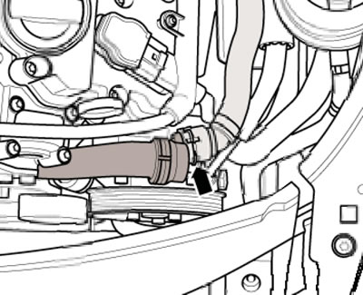
16.9s. Coolant hose on the front coolant pipe
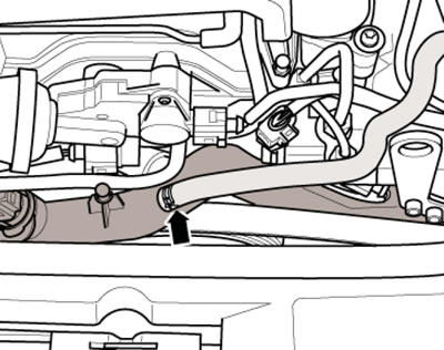
10. Disconnect the power steering fluid pipe (see illustration) from the power steering pump and move it aside.
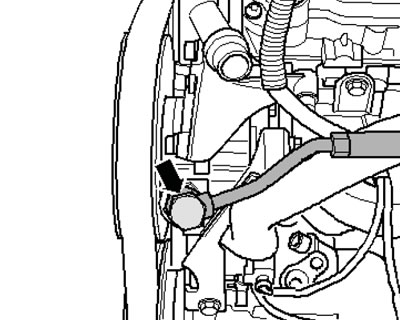
16.10. Power steering line connection
11. Disconnect the CMP sensor connector and move the wiring to the side (see illustration).
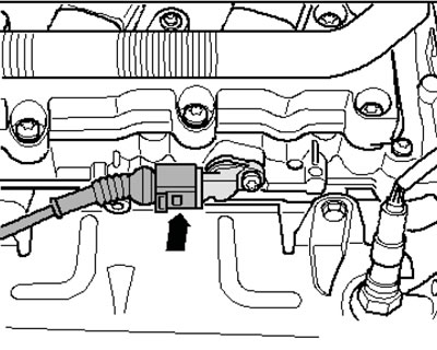
16.11. SMR sensor connector
12. Remove the bolts (1 and 2 in Illustration 16.8) heat shield from above and remove it.
13. Disconnect the connector (2 in illustration 17.18) pre-catalytic lambda probe No.2 and move the wiring to the side.
14. Remove the pre-catalytic lambda probe (1 in the illustration).
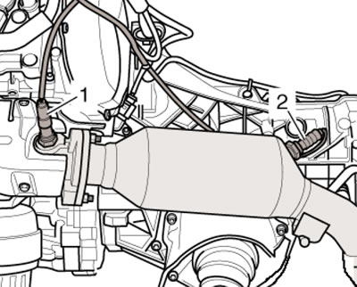
16.14. Lambda probes
15. Give the nuts (1 and 8 in the illustration) and separate the heat shield bracket. Then loosen the nuts (2-7 and 9) and remove the exhaust manifold.
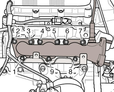
16.15. Sequence of unscrewing the exhaust manifold fasteners
16. Installation is performed in the reverse order of component dismantling. Tighten the exhaust manifold fasteners in the sequence shown in the illustration in two stages: first with a force of 15 Nm, and then with a force of 25 Nm.
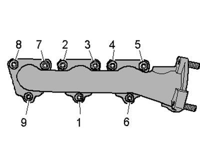
16.16 Sequence of tightening and unscrewing the exhaust manifold fasteners
Diesel engines 2.0L DOHC
17. The details of the exhaust manifold installation are shown in the illustration.
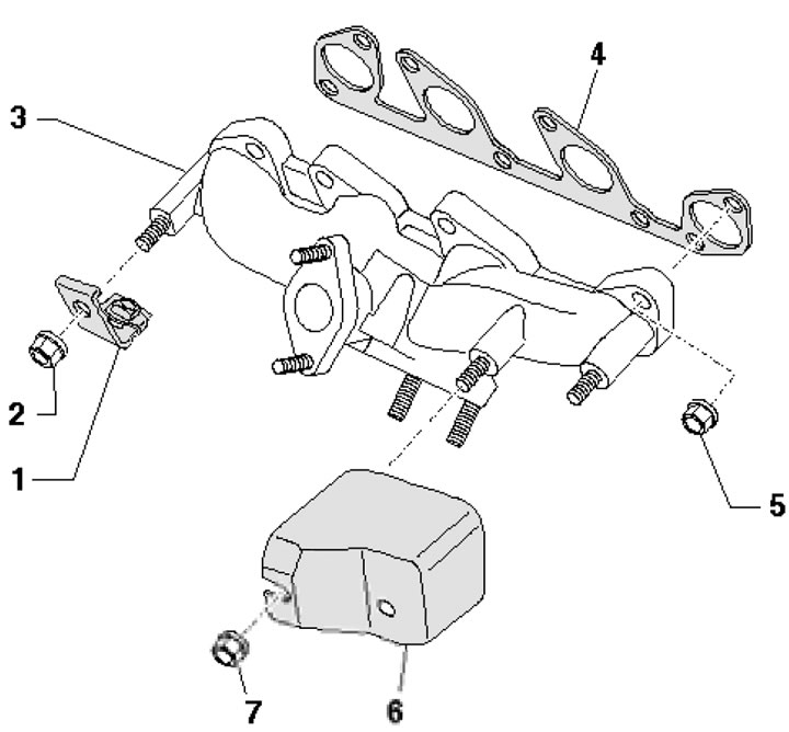
16.17. Exhaust manifold installation details 1. Bracket; 2, 7. Nut, 25 Nm; 3. Exhaust manifold; 4. Gasket, subject to replacement; 5. Nut, 25 Nm, subject to replacement; 6. Heat shield
18. Access to the fasteners is opened after removing the turbocharger (see Part A).