
Repair Chevrolet Repair Toyota Repair Honda Repair AvtoVAZ Repair Mercedes-Benz Repair BMW Repair Opel
Home  |  Contacts  |  Sitemap  |    
English Русский
Български
Беларускі
Український
Српски
Hrvatski
Română
Polski
Slovenský
Magyar
AudiManual.ru


  • AUDI 80
  • AUDI 100
  • AUDI A3
  • AUDI A4
  • AUDI A6
  • AUDI A8
  • AUDI Q
  • OTHER
  • ARTICLES
B8 (2007-2015) B7 (2004-2008) B6 (2000-2006) B6 (2000-2006, petrol) B5 (1994-2001) B5 (1994-2001, petrol)

Replacing the coolant, bleeding the cooling system (Audi A4 B7)

  • Home
  • Audi A4
  • B7 (2004-2008)
  • Power unit
  • Cooling system
  • Replacing the coolant, bleeding the cooling system
            0
Note: If the drained coolant is to be reused, use a clean container to collect the coolant.


1. Remove the expansion tank cap.

4. On models with a drain plug, unscrew the plug (see illustration 17.4 Chapter 2) drain hole on the coolant hose (bottom left) and drain the coolant into a previously prepared container. Tighten the drain plug.

5. On models without a drain plug, remove the retainer (1 in illustration 5.7 Chapter 2) coolant temperature sensor (2) at the radiator outlet, pull the sensor out of the hose connection and drain the coolant into a previously prepared container.

6. On 1.6, 1.8, 2.0 MPI and 3.0 L petrol engines and on 4-cylinder diesel engines, remove the decorative engine cover (see Chapter 2), unscrew the screw (arrow in illustration 5.23 Chapter 2) expansion tank mounts, disconnect the K/L low coolant level sensor connector on the underside of the expansion tank and move the tank to the side without disconnecting the hoses from it. Disconnect the hose from the oil cooler (arrow in the illustration5.24 or 29.13 Chapter 2) and allow the remaining coolant to drain. Reconnect the hose and replace the expansion tank and engine cover.

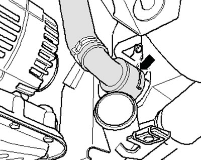
7. On 3.2L engines, disconnect the hoses from the oil cooler to drain the coolant (see illustration 2.7a), and then disconnect the lower hose from the radiator (see illustration 2.7b). Connect the hoses. Use a new sealing ring for the lower radiator hose.
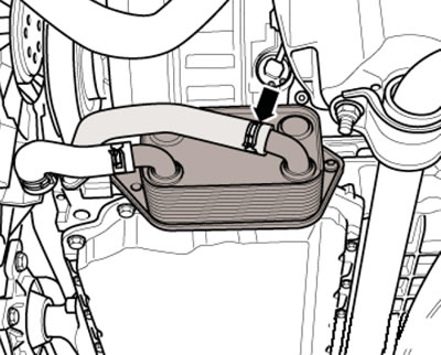
2.7a. Hose on the oil cooler of the 3.2 l engine
2.7a. Hose on the oil cooler of the 3.2 l engine


2.7b. Lower radiator hose retainer

2.7b. Lower radiator hose retainer


8. On 4.2 L engines, to drain the coolant, unscrew the plug in the thermostat housing (see illustration). When tightening the plug, use a new O-ring.

2.8. Drain plug on the thermostat of the 4.2L engine (S4)

2.8. Drain plug on the thermostat of the 4.2L engine (S4)


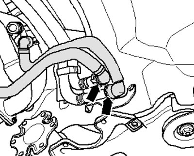
9. On 6-cylinder diesel models, to drain the coolant, disconnect the hoses shown in the illustrations, as well as the lower radiator hose (see illustration 2.7b). Connect the hoses. Use a new sealing ring for the lower radiator hose.
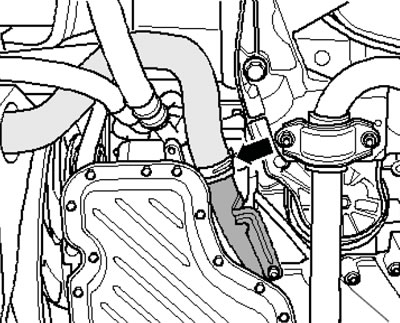
2.9a. Connecting the hose and tube (6-cylinder diesel models)
2.9a. Connecting the hose and tube (6-cylinder diesel models)


2.9b. Coolant hoses behind the engine (6-cylinder diesel models)

2.9b. Coolant hoses behind the engine (6-cylinder diesel models)


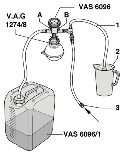
10. Fill the coolant into the reservoir of the VAS6096 cooling system filling device (see illustration). Screw the adapter VAG1274/8 onto the expansion tank instead of the cap, and install the VAS6096 device onto it. Lower the purge hose (1) into a small container (2) to collect the coolant coming out with the air. Close both valves (A and B) and connect the hose (3) to a source of compressed air with a pressure of 6+10 bar.
2.10. Device for filling the cooling system

2.10. Device for filling the cooling system


11. Open the valve (In illustration 2.10), - a vacuum will be created in the cooling system and the pointer on the pressure gauge should move into the green zone. Open valve (A) so that the hose of the VAS6096 tool is filled with coolant and immediately close valve (A). After 2 minutes, during which time a vacuum should be created in the cooling system again and the pointer on the pressure gauge should move into the green zone again, close valve (B). If the pointer on the pressure gauge does not reach the green zone, repeat the procedure from the beginning. If the vacuum drops with the valve closed, check the cooling system for leaks.


12. Disconnect the hose (3 in illustration 2.10) from the compressed air source and open the valve (A), - the coolant from the tank of the VAS6096 device will flow into the cooling system.

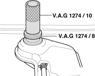
13. Disconnect the VAS6096 tool from the VAG1274/8 adapter and install the VAG1274/10 tube in its place (see illustration)
2.13. Tube on the expansion tank

2.13. Tube on the expansion tank


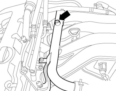
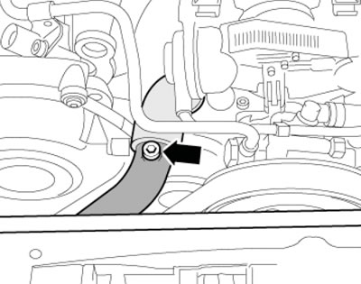
14. On 1.6, 1.8, 2.0 MPI and 3.0L models, as well as on 6-cylinder diesel models, remove the screw (see illustrations) bleed and fill the expansion tank so that the coolant starts to come out through the opened hole. Screw in the screw.

Note: On the 3.0L engine, remove the front of the engine cover to access the screw.

2.14a. Bleed screw on petrol models 1.6, 1.8 and 2.0 MPI
2.14a. Bleed screw on petrol models 1.6, 1.8 and 2.0 MPI


2.14b. Bleed screw on petrol models 3.0 MPI
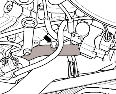
2.14b. Bleed screw on petrol models 3.0 MPI


2.14s. Bleed screw on 6-cylinder diesel models

2.14s. Bleed screw on 6-cylinder diesel models


15. Loosen the hose going to the air conditioning radiator and pull this hose away from the pipe enough to open the bleeding hole (see illustration). Fill the expansion tank so that the coolant starts to come out through this hole without bubbles, install the hose in place and secure it.

Note: On some models, the windshield cowl cover must be removed to access the hose (see Section 15 Chapter 1).
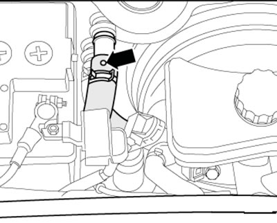

2.15. Air bleed hole on the heater hose

2.15. Air bleed hole on the heater hose


15. On models with additional heating, turn it on for about 30 seconds and close the expansion tank cap.

16. Start the engine, set the maximum temperature of the climate system for both zones and let the engine run for about 3 minutes at 2000 rpm. Then let the engine run at idle speed until both radiator hoses are warm. Finally, let the engine run for one minute at 2000 rpm, turn off the ignition and let the engine cool down.

17. Check and, if necessary, adjust the coolant level (see Section 4 Chapter 1).

(The article is a reprint of material from «AudiManual»)
The article was checked by auto expert Timur Bazhenov
This article is available at russian, bulgarian, belarusian, ukrainian, serbian, croatian, romanian, polish, slovak, hungarian

Share information:
Previous articles
Audi A4 B7: Cooling system
Next articles

General information and precautions
Engine Cooling and Cabin Air Conditioning Systems —…
Removal and installation the radiator shroud and fan assembly
Removal and installation the radiator
Checking, removing and installing the thermostat
Removal and installation the water pump


Similar articles on other Audi car models:
Troubleshooting the cooling system Audi 80 B3 (1986-1991, petrol)
Cooling system specifications Audi 100 C3 (1982-1990, diesel)
Checking the functioning of the cooling system Audi A3 Type 8L (1996-2003)
Scheme 2.13. Cooling system, radiator fan relay, coolant pump… Audi A6 C5 Allroad (1999-2005)
Engine cooling system Audi A8 D2 (1994-2002)
Replacing the coolant, checking and adjusting its level,… Audi Q7 Typ 4L (2005-2015, diesel)
Cooling system — checking and refilling fluid Audi A2 (1999-2005)
Link to this page in different formats


Visitor comments

No comments yet


How much will 15 + 10 =


A4(B8, 2007-2015) 
  • General information
  • Operating instructions
  • Power unit
  • Petrol engines 1.8 l
  • Petrol engines 1.8/2.0 l
  • Petrol engines 3.0 l
  • Petrol engines 3.2 l
  • Fuel system (petrol)
  • Diesel engines 2.0 l (CA*)
  • Diesel engines 2.0 l (CJCB)
  • Diesel engines 2.7/3.0 l
  • Diesel engines 3.0 l
  • Fuel system (diesel)
  • Transmission
  • Manual gearbox 0B1
  • Manual gearbox 0B2
  • Manual gearbox 0B3
  • Manual gearbox 0B4
  • Automatic transmission 0B5
  • Automatic transmission 0B6
  • Automatic transmission 0AW
  • All-wheel drive system
  • Chassis
  • Front suspension
  • Rear suspension
  • Brake system
  • Steering system
  • Body
  • Exterior
  • Interior
  • Seats
  • Doors, locks and windows
  • Security system
  • Heating and air conditioning
  • Electrical equipment
  • Audio system
  • Power devices
  • Equipment and devices
  • Lighting and lamps
  • Electrical circuits
 
A4(B7, 2004-2008) 
  • General information
  • Introduction to manual
  • Troubleshooting
  • Operating instructions
  • Maintenance
  • Power unit
  • Petrol engines 2.0 (ALT)
  • Petrol engines 2.0 (TFSI)
  • Petrol engines 1.8 (MPI)
  • Diesel engines
  • Cooling system
  • Air conditioner
  • Fuel and exhaust system
  • Ignition system
  • Starting and charging
  • Transmission
  • Clutch
  • Manual gearbox
  • Automatic gearbox
  • Drive shafts
  • Chassis
  • Brake system
  • Front suspension
  • Rear suspension
  • Steering
  • Body
  • Exterior
  • Interior
  • Electrical equipment
  • Equipment and devices
  • Lighting and signaling
  • Windscreen wipers and washers
  • Electrical diagrams
  • Electrical diagrams (since 2007)
 
A4(B6, 2000-2006) 
  • General information
  • Vehicle Description
  • User manual
  • Maintenance
  • Power unit
  • Gasoline engine
  • Diesel engine
  • Lubrication system
  • Cooling system
  • Supply system
  • Injection system
  • Exhaust system
  • Ignition and control
  • Transmission
  • Gear box
  • Clutch and drive shafts
  • Chassis
  • Brake system
  • Car suspension
  • Steering
  • Body
  • Heating and ventilation
  • Exterior (external elements)
  • Interior (internal elements)
  • Electrical equipment
  • Power devices
  • Lighting and appliances
  • Electrical circuits
 
A4(B6, 2000-2006, petrol) 
  • General information
  • Introduction to the guide
  • Car care
  • Power unit
  • Engine repair
  • Lubrication system
  • Cooling system
  • Injection and control system
  • Ignition system
  • Power and exhaust system
  • Transmission
  • Clutch and drive shafts
  • Car gearbox
  • Chassis
  • Suspension and wheels
  • Steering
  • Brake system
  • Body
  • Interior
  • Exterior
  • Electrical equipment
  • Equipment and devices
  • Lighting and signaling
  • Power devices
  • Electrical circuits
 
A4(B5, 1994-2001) 
  • General information
  • Introduction to the guide
  • Car care
  • Maintenance (gasoline)
  • Maintenance (diesel)
  • Power unit
  • Gasoline engines
  • Diesel engines
  • Engine overhaul
  • Cooling system
  • Fuel injection (gasoline)
  • Fuel system (diesel)
  • Exhaust system
  • Ignition system
  • Transmission
  • Clutch
  • Mechanical gearbox
  • Automatic gearbox
  • Drive shafts
  • Chassis
  • Brake system
  • Car suspension
  • Steering
  • Body
  • Exterior
  • Interior
  • Doors, locks and windows
  • Heating and ventilation
  • Electrical equipment
  • Power devices
  • Equipment and devices
  • Electrical circuits
 
A4(B5, 1994-2001, petrol) 
  • General information
  • Vehicle description
  • Maintenance
  • Power unit
  • Engine repair
  • Turbocharging
  • Exhaust system
  • Cooling system
  • Ignition system
  • Fuel system
  • Motronic injection system
  • MPI and MPFI injection system
  • Transmission
  • Clutch
  • Gearbox and shafts
  • Chassis
  • Steering
  • Car suspension
  • Brake system
  • Wheels and tires
  • Body
  • Heating and ventilation
  • Body parts
  • Electrical equipment
  • Fuses and relays
  • Power devices
  • Lighting and lamps
  • Tools and devices
  • Electrical circuits
 
AudiManual.ru © 2017-2026 · Mobile version · Feedback · Sitemap: EN BG BY UA RS HR RO PL SK HU · Site search · News and articles
80 B2 · 80 B3 petrol · 80 B3 · 80 B4 · 100 C3 diesel · 100 C3 petrol · 100 C3 · 100 C4 petrol · 100 C4 · A3 Type 8L · A4 B5 petrol · A4 B5 · A4 B6 petrol · A4 B6 · A4 B7 · A4 B8 · A6 C4 · A6 C5 · A6 C5 Allroad · A8 D2 · Q5 Type 8R · Q7 Typ 4L · Audi A2 ·
This site uses cookies 🍪. Click the button to accept this fact.