



Note: The engine is removed forward without the transmission with the radiator frame removed. When installing the engine, do not forget to return all removed or cut electrical wiring fasteners to their original places.
1. Follow the steps described in paragraphs 1-6 Section 5.
2. Press the latches (see illustration 17.3) and remove the air ducts of the left and right intercoolers.
3. Place a tray under the engine.
On models with a threaded coolant drain plug, unscrew the plug on the coolant hose under the radiator, disconnect the connector on the coolant temperature sensor at the radiator outlet and release the wiring. On models without a threaded coolant drain plug, remove the clamp (1 in illustration 5.7) on the coolant temperature sensor (2) at the radiator outlet, remove the sensor from the pipe and drain the coolant. Put the wiring aside.
4. Remove the lower engine cooling system hose from the radiator (see illustration 5.8).
5. Disconnect the lower air duct (1 in illustration 18.6) from the intercooler and release the coolant line from the holder (2).
Note: Do not open the refrigerant circuit.
6. Disconnect the air duct (1 in the illustration) turbocharger from the radiator frame in the lower right corner.
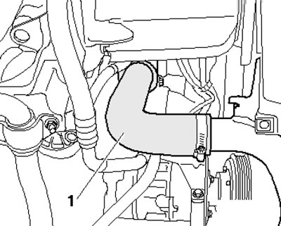
29.6. Turbocharger air duct
7. Clamp the hoses near the power steering fluid radiator using clamps No.3094 (see illustration 5.9), place a tray under the hose connection and disconnect the hoses.
8. On models with AT, place a tray under the connection points (see illustration) aTF lines, unscrew the connecting nipples (1 and 2) and disconnect the ATF lines. Unscrew the bolt (arrow) and separate the ATF lines from the engine.
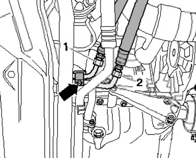
29.8. ATF Line Connections and Fasteners
9. Release the fasteners (arrows in the illustration) and remove the top engine cover.
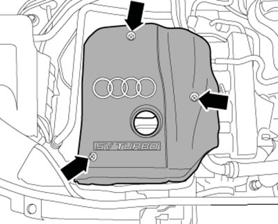
29.9. Fastening the upper engine cover
10. Perform the actions described in paragraphs 11-20 Section 5.
11. Disconnect the vacuum hose from the engine compartment bulkhead (3 in the illustration) brake booster, vacuum hose (1) EVAP solenoid valve and ground wire (2).
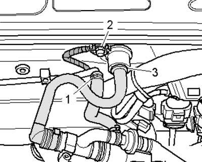
29.11. Engine compartment bulkhead connections
12. Remove the cooling system hoses (1 and 3 in Illustration 5.23), unscrew the expansion tank mounting screw (arrow) and move it to the side. Disconnect the K/L low coolant level sensor connector on the bottom of the expansion tank.
13. Place under the connection (see illustration) oil cooler water hose pan, disconnect this hose from the oil cooler and drain the remaining coolant.
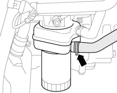
29.13. Water hose on the oil cooler
14. Disconnect the coolant hose (see illustration 5.31), leading to the air conditioning radiator, on the left side of the pipe, and the air conditioning radiator hose on the right side of the cylinder head.
15. Disconnect the coolant hose from the thermostat (see illustration) and coolant hose (1 in illustration 5.25b) from the upper water pipe.
Note: The one shown in the illustration 5.25b paragraph 2 do not take into account.
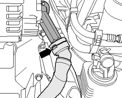
29.15. Coolant hose on thermostat
16. Disconnect the air duct (1 in the illustration) from the intake manifold, disconnect the connector (2) of the boost pressure sensor and move the wiring to the side.
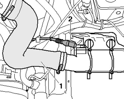
29.16. Air duct (1) of the intake manifold and connector (2) of the boost pressure
17. If connected, disconnect the vacuum hose (arrow on the illustration), leading to the vacuum receiver, and move the hose to the side. 18 Mark the direction of rotation on the alternator belt with chalk or a felt-tip pen so that you can install the belt in the same way later. Loosen the belt tension by turning the tensioner in the direction of the arrow (see illustration 5.26), and remove it.
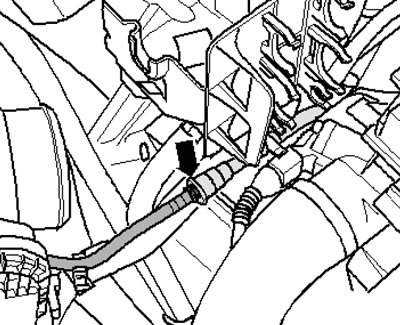
29.17. Vacuum hose
19. Turn out the front (see illustration 5.27a) and rear (see illustration 5.27b) power steering pump mounting bolts. Remove the power steering pump and place it on the side member without disconnecting the power steering fluid lines.
20. Disconnect the connector (bottom arrow in the illustration) sAI pump and move the wiring to the side.
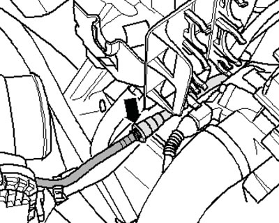
29.20. SAI pump connector and SAI hose
21. Disconnect the connector (3 in the illustration) eVAP valve solenoid and air flow meter wiring connector (5), disconnect hoses (1, 4, 6 and 7), remove the retainer (2) and detach the air cleaner housing.
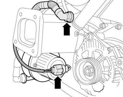
29.21. Cylinder head connectors and hoses
22. Disconnect the fuel line (1 in the illustration) and take her aside.
Note: Ignore position 2.
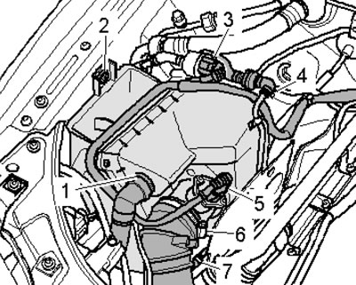
29.22. Fuel lines
23. Perform the actions described in paragraphs 32-39 Section 5.
24. Remove the turbocharger mounting nuts from the catalytic converter (see illustration).
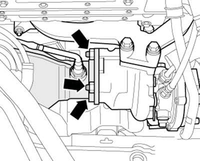
29.24. Fastening the turbocharger to the catalytic converter
25. Remove the heat shield (1 in illustration 5.43) of the inner CV joint of the right drive shaft.
26. Perform the actions described in paragraphs 41, 42, 46-50 Section 5.
27. On models with AT 01V, remove three bolts (arrows in the illustration) torque converter mounts through the starter mounting hole using a 15 mm head. To access the bolts, turn the crankshaft clockwise using the central bolt.
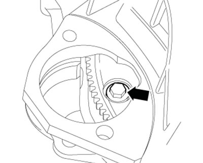
29.27. Torque converter mounting bolt
28. Perform the actions described in paragraphs 51-53 of Section 5.
29. Install puller No.10-222A on the wing flanges behind the struts (the lead screws are located in the front) and secure the mounting fixture for #3147 in the bolt holes at the top of the transmission dome as shown in the accompanying illustration. Connect jig #3147 and crossmember #10-222A with hook #10-222A/12 and slightly lift the engine with the crossmember lead screws.
Note: For better presentation, the engine is not shown in the illustration.
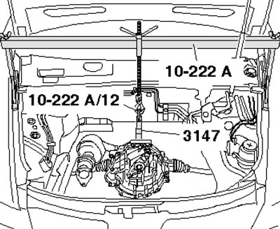
29.29. Hanging the transmission
30. Release the eye on the rear side of the engine, hang the engine lifting tool No.2024A on the engine using crane No. VAG 1202A or No. VAS 6100 (see illustration 5.55).
Note: To align the center of gravity of the power unit, the hook bars must be inserted as shown in the illustration. The hooks and locking pins of the hanging device must be secured with pins (see arrows).
31. Remove the last bolt on the engine/transmission connection flange, make sure all hoses and wiring between the engine and the body are disconnected. Lift the engine through the threaded bolts from the support pads. Tighten the traverse lead screws #10-222A (see illustration 29.29), separate the engine from the transmission and pull it forward out of the engine compartment. Make sure that the cables on the front wall of the body are not damaged. On models with automatic transmission, when separating the automatic transmission from the engine, simultaneously separate the torque converter from the drive disk (see illustration) and secure the torque converter in the AT with clamps so that it does not fall out.
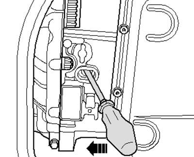
29.31. Separating the torque converter from the drive disk
32. Perform the actions described in paragraphs 57-59 Section 5.
33. On models with manual transmission:
- when installing a new clutch disc in conjunction with an old self-adjusting pressure plate, the pressure plate adjusting ring should be turned to the stop, otherwise the pressure plate will operate with reduced contact pressure (the clutch is slipping);
- if the clutch disc is not being changed, do not turn the adjusting ring; the new self-adjusting pressure plates are already pre-set and do not require adjustment;
- check the clutch release bearing for wear, replace it if necessary (see Chapter 6);
- lightly lubricate the gearbox input shaft teeth with G 000 100 grease (do not lubricate the clutch release bearing guide bushing);
- if necessary, check the centering of the clutch driven disc;
- check the clutch release bearing for wear and replace it if necessary;
- if the plastic ring of the release bearing is not tightly fitted, glue the plastic ring to the bearing ring using AMV 195 KD1 01 glue, - three rectangular protrusions (arrows in illustration 5.60) plastic rings will fall into the grooves of the bearing ring; if the grooves are deeper than 0.5 mm, replace the clutch release bearing;
- the engine must have a needle bearing installed on the crankshaft - install the bearing if necessary.
34. On models with AT 01V:
- make sure there is no needle bearing on the crankshaft, remove the bearing if necessary;
- to secure the torque converter to the drive disc, use only bolts specifically designed for this purpose;
- if the torque converter is installed correctly, the distance between the rear contact surface on the torque converter studs and the contact surface on the torque converter dome (see illustration) should be approximately 23 mm;
- if the torque converter is installed incorrectly, its drive lugs and the torque converter pump will be damaged.
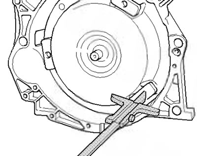
29.34. Checking the position of the torque converter
35. Check that the intermediate shield is suspended on the flange and the mounting bushings are fitted (see illustration 5.61).
36. Mate the engine to the transmission and tighten one bolt by hand.
37. Tighten the lead screws of the crosshead No.10-222A (see illustration 29.29) and lower the engine, while installing the threaded bolt of the engine mount and engine mount console.
38. Install the engine mounts without tension. To do this, before tightening the mount bolts, move the engine to align its position.
39. After installation, check the engine oil, transmission oil and power steering fluid levels (see Chapter 1).
40. Fill the cooling systems (see Chapter 3).
Note: Drained coolant may only be reused if it is clean and the cylinder head or cylinder block has not been replaced.
41. Tighten threaded connections with the following forces:
- torque converter to drive disk 85 Nm
- engine mount to console and engine support 23 Nm
- terminal B+ and starter 16 Nm
- heat protective
- cV joint screen 23 Nm
- fuel line on the distribution line 22 Nm
- thrust support stop
- to radiator frame 28 Nm
- other details (thread M6 //M7 // M8) 9 // 15 // 20 Nm
- other details (thread M10 // M12) 45//65 Nm.