
Note: The engine is removed forward without the transmission with the radiator frame removed. When installing the engine, do not forget to return all removed or cut electrical wiring fasteners to their original places.
1. On models with AT or CVT, place the selector lever in the "N" position.
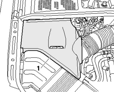
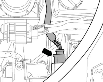
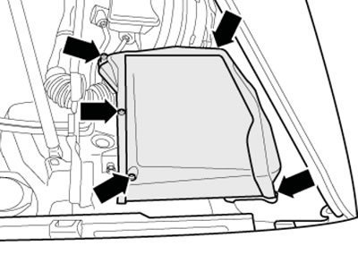
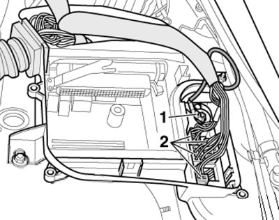
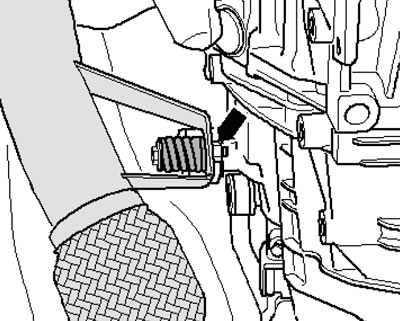
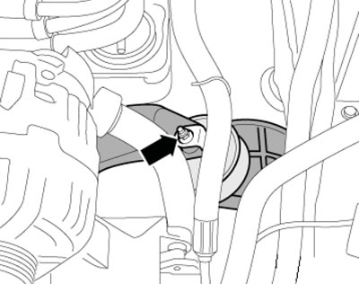
2. Remove the rubber seal of the water drainage box casing in the direction of the arrow (see illustration), where provided, remove the water drainage box casing (1).
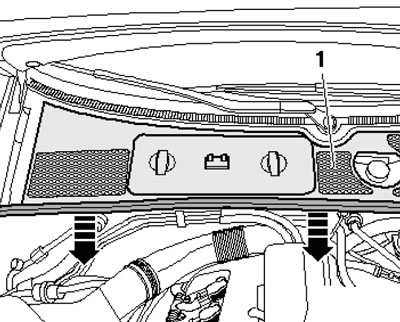
5.2. Removing the water-drainage box casing and its seal (models with number up to 8EZ5A 400001)
3. Disconnect the negative cable from the battery, remove the cap from the engine cooling system expansion tank and remove the front wheels.
4. On models with independent/additional heating, unscrew the bolts (arrows in the illustration) its exhaust pipe from the soundproofing screen.
5.4. Heater screws on the soundproofing screen
5. Unscrew the fasteners (1 and 2 in the illustration) and remove the front sound insulation screen. Where present, loosen the quick-release couplings (3) and remove the rear sound insulation screen.
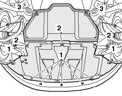
5.5. Fastening the front soundproofing screen
6. Unscrew the fastener of the soundproofing screen holder (see illustration) and remove the front bumper cover (see Chapter 11).
5.6. Fastening the soundproofing screen holder
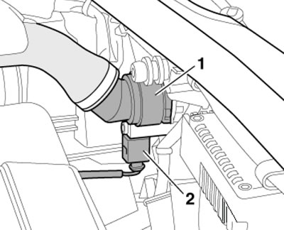
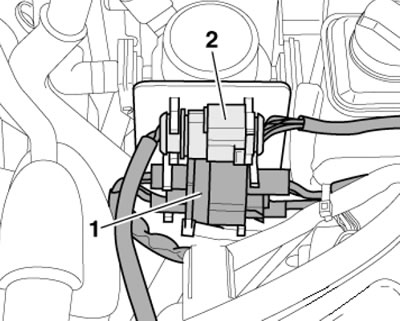
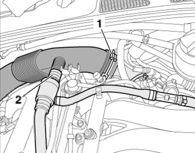
7. Place a drain pan under the engine. On models with a threaded coolant drain plug, unscrew the plug on the coolant hose under the radiator, disconnect the connector on the coolant temperature sensor at the radiator outlet and release the wiring. On models without a threaded coolant drain plug, remove the clamp (1 in the illustration) on the coolant temperature sensor (2) at the radiator outlet, remove the sensor from the pipe and drain the coolant. Put the wiring aside.
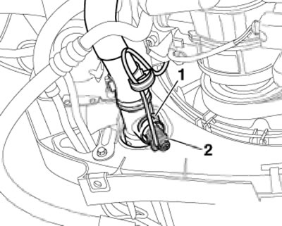
5.7. Removing the coolant temperature sensor at the radiator outlet
8. Remove the lower engine cooling system hose from the radiator (see illustration).
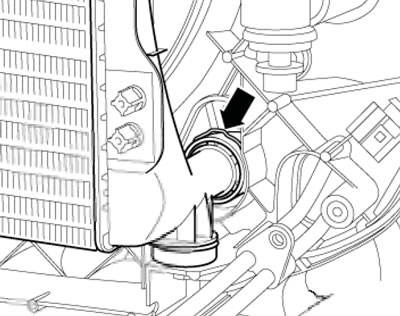
5.8. Connecting the lower radiator hose
9. Clamp the hoses near the power steering fluid radiator using clamps No.3094 (see illustration), place a tray under the hose connection and disconnect the hoses.
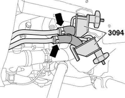
5.9. Power steering fluid cooling hoses
10. On CVT models, place a tray under the connection points (see illustration) CVT oil lines going to the radiator and disconnect them.
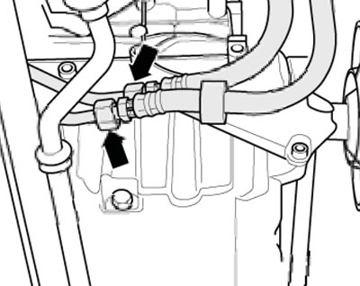
5.10. CVT Oil Cooling Hoses
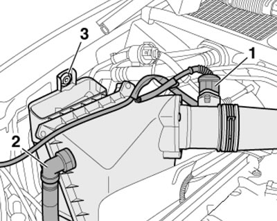
11. If there is a casing (1 in the illustration) on the right side of the engine compartment, remove this cover.
5.11. Overlay on the right side of the engine compartment
12. Disconnect the EVAP valve solenoid connector (1 in the illustration) and remove the solenoid valve. Unscrew the screws (arrows) and remove the air duct (2).
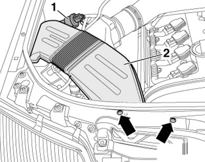
5.12. EVAP solenoid valve (1) and air duct fasteners (2)
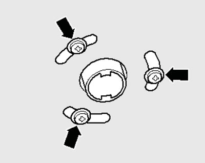
13. Squeeze and remove the protective cover of the power steering fluid reservoir (see illustration).
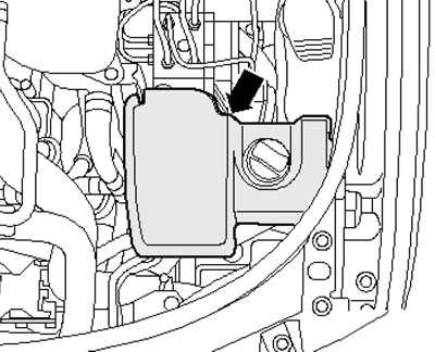
5.13. Power steering fluid reservoir casing
14. Remove the upper hose from the radiator (1 in the illustration) engine cooling system, disconnect the connectors (2) of the left and right frontal impact sensors on the radiator frame.
5.14. Upper radiator hose frontal impact sensor connector
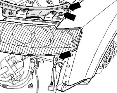
15. Disconnect the electrical wiring connectors of both headlights (see illustration).
5.15. Headlight wiring connector
16. Remove the connectors (1 and 2 in the illustration) from the bracket, disconnect them and put the wiring aside.
5.16. Connectors on the bracket
17. Remove the screws (see illustration) and remove the right and left air ducts from the radiator.
5.17. Air duct on the left side of the radiator
18. Release the outside temperature sensor (2 in the illustration) from the holder, unscrew the bolts (3 and 4) and remove the power steering fluid radiator. Disconnect the connector (1) on the high pressure sensor, unscrew the mounting bolts of the refrigeration unit condenser and lower it down together with the refrigerant lines.
Caution: Do not disconnect refrigerant lines or allow them to be stressed or kinked.
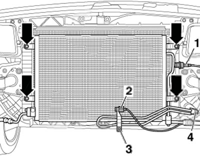
5.18. High pressure sensor (1), outside temperature sensor (2), power steering radiator fasteners (3 and 4) and condenser (arrows)
19. Remove the bolts on the left and right sides of the radiator frame (see illustration), disconnect the cable drive from the hood lock and remove the engine compartment seal on the radiator frame and on the connecting edges of the wings.
5.19. Engine compartment seal fastener
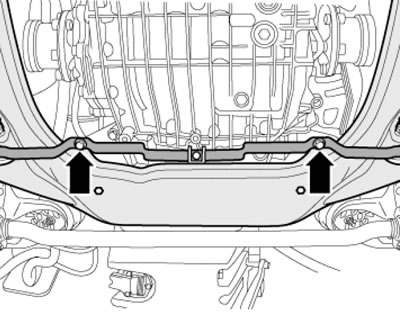
20. Remove the bolts (arrows in the illustration) on the left and right front bumper buffers, and remove the buffers. With the help of an assistant, remove the radiator frame and place it aside in a stable position.
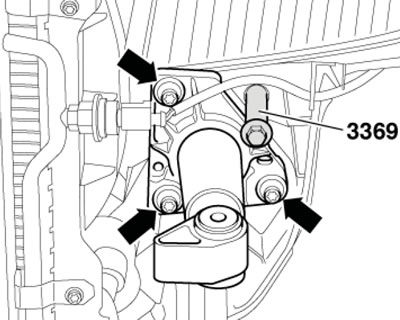
5.20. Fastening the front bumper buffer
Note: Ignore the #3369 fixture shown in the illustration.
21. Remove the decorative (upper) engine cover upwards (see illustration).
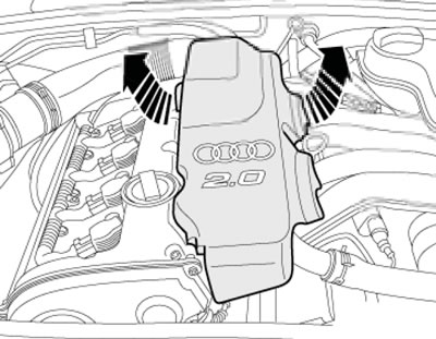
5.21. Removing the top engine cover
22. Disconnect the brake booster vacuum line at the ejector pump (3 in the illustration), disconnect the EVAP solenoid valve vacuum hose (1) and loosen the ground wire nut (2) on the bulkhead.
5.22. Vacuum hoses (1 and 3) and ground connection (2)
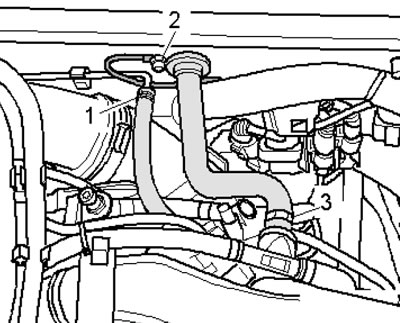
23. Remove the cooling system hoses (1-3 in the illustration), remove the expansion tank mounting screw (arrow) and set it aside. Disconnect the K/L low coolant level sensor connector on the underside of the expansion tank.
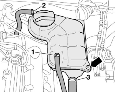
5.23. Removing the expansion tank
24. Place under the connection (see illustration) oil cooler water hose pan, disconnect this hose from the oil cooler and drain the remaining coolant.
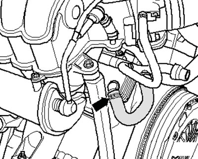
5.24. Coolant hose on the oil cooler
25. Remove the hoses (1 in the illustrations) coolant.
Note: Please ignore item 2 shown in the illustrations.
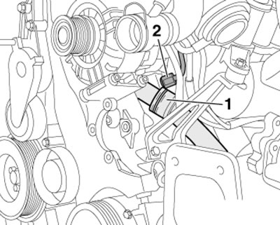
5.25a. Coolant hose
5.25b. Coolant hose
26. Mark the alternator belt with chalk or a felt-tip pen to indicate the direction of rotation so that you can install the belt in the same way. Loosen the belt tension by turning the tensioner in the direction of the arrow (see illustration), and take it off.
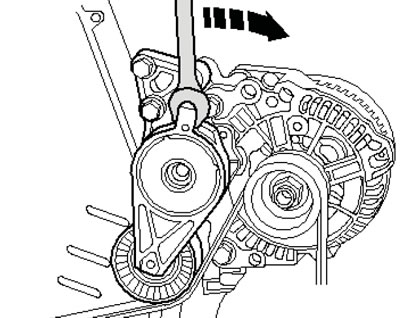
5.26. Removing the alternator drive belt
27. Turn out the front (see illustration 5.27a) and back (see illustration 5.27b) power steering pump mounting bolts. Remove the power steering pump and place it on the side member without disconnecting the power steering fluid lines.
5.27a. Front power steering pump mounting bolts
5.27b. Rear power steering pump mounting bolt
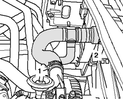
28. Disconnect the air ducts (1 and 2 in the illustration), and also a hose on the underside of the duct.
5.28. Air duct connections
29. Disconnect the connector (1 in the illustration) air flow meter, remove the hose (2, if available) and remove the air cleaner housing by removing the spring clip (3).
5.29. Air flow meter connector (1), air cleaner hose (2) and fastener (3)
30. Wrap a rag around the fuel supply line connection and slowly loosen its union nut to relieve fuel pressure (while the fuel is leaking out). Completely disconnect and release the fuel supply line (2 in the illustration), as well as the return fuel line (1).
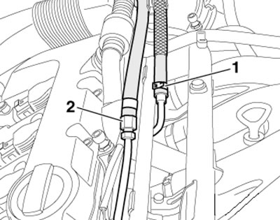
5.31. Fuel supply line (2) and fuel return line (1)
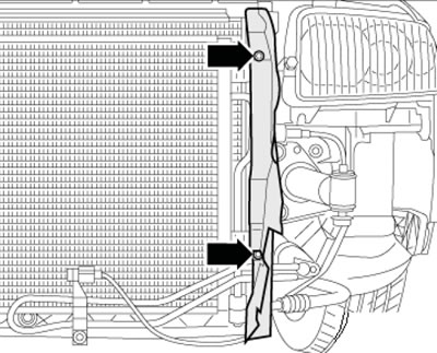
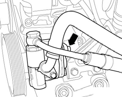
31. Remove the hose from the branch pipe (arrow on the illustration), going to the air conditioning radiator. Remove the air conditioning radiator hose from the cylinder head pipe by releasing the fastening brackets on the connecting flange from the clamps.
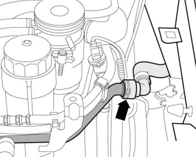
5.31. Cooling system hose
32. Use a screwdriver to pry up and remove both protective caps (3 in the illustration), loosen the nuts (4) a few turns and loosen the wiper arms (2) by slightly rocking the axle. Loosen the nuts (4) completely and remove the wiper arms, then remove the safety clip (1) and the windshield fairing grille (5).
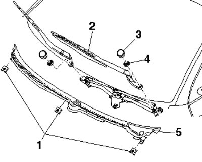
5.32. Removing the windshield fairing
33. Remove the cover of the mounting block in the water drainage box (see illustration).
5.33. Mounting block cover fastening
34. Use a screwdriver to lift the bracket (see illustration).
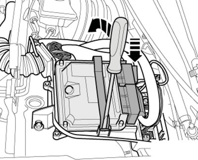
5.34. ECM mounting bracket
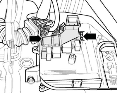
35. Press the clamps (arrows in the illustration) and disconnect the ECM connectors (1 and 2).
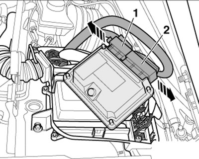
5.35. ECM Wiring Connectors
36. On ECM (1 in the illustration) with the protective housing (4) the connectors remain connected. Place the ECM on the engine and secure it from falling.
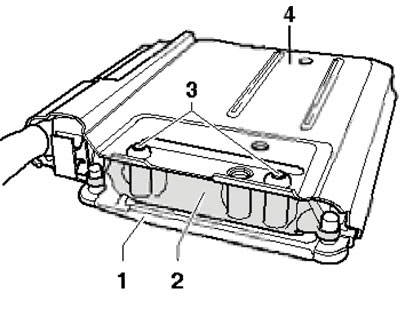
5.36. ECM with protective housing
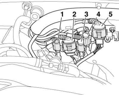
37. Disconnect all electrical wiring connectors (2 in the illustration) using spark plug pliers (vAG 1922 device) and disconnect the wire (1).
5.37. Connectors in the mounting block
38. Unlock the latches (see illustration) and remove the additional relay bracket from the mounting block in an upward direction.
5.38. Additional relay bracket clamps
Disconnect the engine wiring harness from the mounting block and engine compartment bulkhead and lay it loosely.
39. Remove the connectors (2 and 5 in the illustration) from the left bulkhead mount, disconnect these connectors and remove the connector bracket from the bulkhead.
5.39. Connectors on the engine compartment bulkhead
40. Remove the catalytic converter fasteners from the exhaust manifold (see illustration).
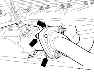
5.40. Fastening the catalytic converter to the exhaust manifold
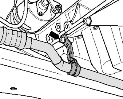
41. Give the nut (see illustration) bracket of the inlet pipe.
5.41. Nut of the bracket of the inlet pipe
Note: The flexible section of the intake pipe must not be bent more than 10°, otherwise it may be damaged.
42. Loosen the clamping sleeve mounting nuts (see illustration), slide the clamp back and remove the catalytic converter.
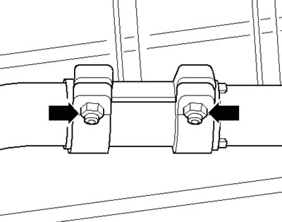
5.42. Connecting the catalytic converter to the exhaust pipe
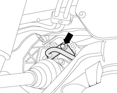
43. On CVT models, remove the heat shield (1 in the illustration) inner CV joint of the right drive shaft.
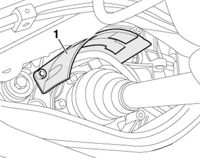
5.43. Heat shield of the CV joint of the right drive shaft (models with CVT)
44. On CVT models, loosen the nut (2 in the illustration) and remove the ATF line bracket from the engine.
Note: Ignore position 1 in the illustration.
5.44. Nut (2) of the ATF line bracket (models with CVT)
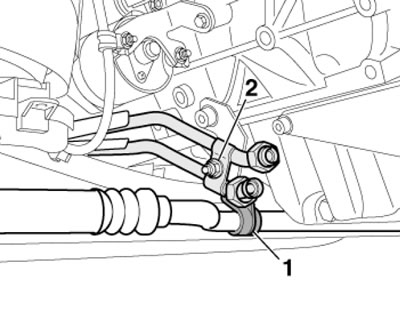
45. On CVT models, place a pan under the ATF line connection and remove the bolt (see illustration) and remove the ATF lines.
5.45. Fastening the ATF line connection (models with CVT)
46. Disconnect the speedometer sensor connector on the left side of the gearbox (bottom arrow in the illustration). On models with manual transmission, disconnect the connector of the reversing lights (top arrow). Set the electrical wiring aside.
5.46. Transmission connectors
47. Disconnect the engine oil level and temperature sensor connector (see illustration).
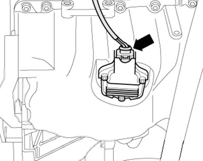
5.47. Engine oil temperature and level sensor connector
48. Remove the refrigerant line bracket mounting bolt from the oil pan (see illustration).
5.48. Fastening the refrigerant line bracket
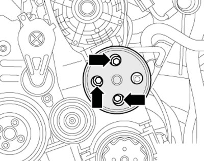
49. Disconnect the connector (1 in the illustration) wiring of the electromagnetic clutch of the air conditioning system compressor, unscrew the bolts (arrows) securing the compressor to the bracket and hang the compressor on the body without disconnecting the refrigerant lines from it.
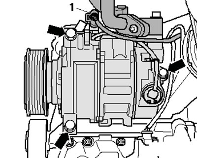
5.49. Compressor connector (1) and fasteners (arrows)
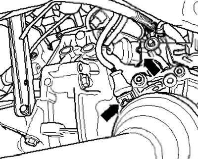
50. Give the nut (1 in the illustration) ground wires on the right engine support, disconnect the wiring (2 and 3) from the starter and remove the insulator on the positive starter connection terminal. Loosen the nut (4) securing the clamp, unscrew the bolt (5) of the starter holder and remove the starter from the transmission.
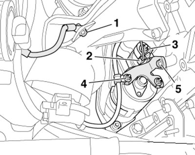
5.50. Removing the starter
51. Mark the mounting position of the connections (1 in the illustration) and fixing bushings (2) at the bottom on the right and left engine support cushions.
Note: Different engines have different mounting holes. Loosen the nuts (1) from the bottom of the left and right mounts.
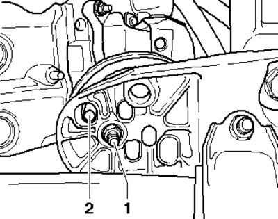
5.51. Lower nuts of engine support cushions
52. Remove the bolts (see illustration), which are accessible from below on the engine-transmission connection flange.
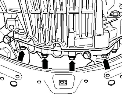
5.52. Lower transmission-to-engine mounting bolts
53. Loosen the top nut a few turns (see illustration) on the left engine mount. Unscrew the upper bolts of the engine-transmission connection flange, leaving one bolt screwed in by hand.
5.53. Upper nut of the left engine support
54. Install puller #10-222A on the connecting edges of the wings (the lead screws are located in the front) and secure the mounting fixture for #3147 in the bolt holes on the left and right side of the transmission dome as shown in the illustration. Connect jig #3147 and crossmember #10-222A with hooks #10-222A/2 and slightly lift the engine using the crossmember lead screws.
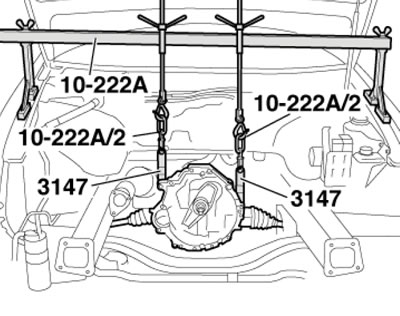
5.54. Transmission lifting device
Note: For better presentation, the engine is not shown in the illustration.
55. Release the eye on the rear side of the engine, hang the tool No.2024A for hanging from the engine on the crane No. VAG 1202A or No. VAS 6100 (see illustration).
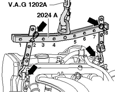
5.55. Engine lifting device
Note: To align the center of gravity of the power unit, the hook bars must be inserted as shown in the illustration. The hooks and locking pins of the hanging device must be secured with pins (see arrows).
56. Remove the last bolt on the engine/transmission connection flange, make sure all hoses and wiring between the engine and the body are disconnected. Lift the engine through the threaded bolts from the support pads. Tighten the lead screws of the crossmember No.10-222A (see illustration 5.54), separate the engine from the transmission and pull it forward out of the engine compartment, making sure that the cables on the front wall of the body are not damaged.
57. Installation is carried out in the reverse order of dismantling the components. Please keep the following information in mind.
58. Use new self-locking nuts and bolts/screws, as well as bolts/screws tightened to a certain angle. Use new O-rings, lip seals and gaskets. Use clamps of the appropriate series to secure all hose connections. All cable ties must be installed in their original positions.
59. On CVT models, clean the splines of its input shaft and flywheel damper from dirt and rust, apply a very thin layer of G 000 100 grease to them. Be sure to remove excess grease.
60. On models with manual transmission:
- check the clutch release bearing for wear, replace it if necessary (see Chapter 6);
- lightly lubricate the teeth of the manual transmission input shaft with G 000100 grease (do not lubricate the clutch release bearing guide bushing);
- if necessary, check the centering of the clutch driven disc;
- check the clutch release bearing for wear and replace it if necessary;
- if the plastic ring of the release bearing is not tightly fitted, glue the plastic ring to the bearing ring using AMV 195 KD1 01 glue - three rectangular protrusions (arrows in the illustration) plastic rings will fall into the grooves of the bearing ring; if the grooves are deeper than 0.5 mm, replace the clutch release bearing;
- the engine must have a needle bearing installed on the crankshaft - install the bearing if necessary.
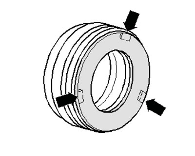
5.60. Protrusions on the plastic ring
61. Check that the intermediate shield is suspended on the flange and the mounting bushings are fitted (see illustration).
5.61. Mounting bushings and shield on the engine-transmission connection flange
62. Mate the engine to the transmission and tighten one bolt by hand.
63. Tighten the lead screws of crosshead No.10-222A (see illustration 5.54) and lower the engine, while installing the threaded bolt of the engine mount and engine mount console.
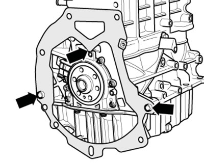
64. Tighten the bolts to the torques specified in the captions to the accompanying illustrations.
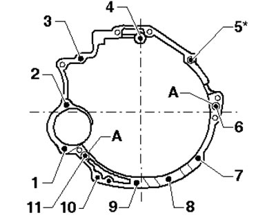
5.64a. Fastening the manual transmission to the engine 1, 4. Bolts M 12x75, 65 Nm; 2. Bolt M 12x90, 65 Nm; 3. Bolt M 12x75, 65 Nm*; 5. Bolt M 12x110, 65 Nm*; 6. Bolt M 12x110, 65 Nm; 7-10. Bolts M 10x45, 45 Nm; 11. Bolt M 12x130, 65 Nm; A. Centering bushings
*A wiring harness bracket must be installed at the same time
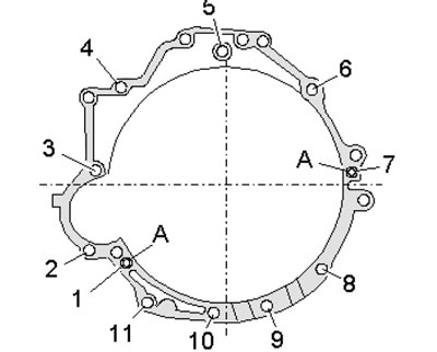
5.64b. Fastening the CVT to the engine 1. Bolt M 12x90, 65 Nm; 2. Bolt M10x60, 45 Nm; 3. Bolt M 12x67, 65 Nm; 4. Bolt M 12x75, 65 Nm*; 5. Bolt M 12x75, 65 Nm; 6. Bolt M 12x110, 65 Nm*; 7. Bolt M 12x80, 65 Nm; 8. Bolt M10x50, 45 Nm; 9-11. Bolts M 10x45, 45 Nm; A. Centering bushings
*A wiring harness bracket must be installed at the same time
Note: The tightening torques given are ±15% and are valid for lightly greased, phosphated or oxidized nuts and bolts. Always use new bolts/nuts to secure the CVT. Additional lubricants, such as engine or transmission oils, are permitted, except for those containing graphite. Do not use degreased parts.
65. Install the engine mounts without tension. To do this, before tightening the mount bolts, move the engine to align its position.
66. After installation, check the engine oil, transmission oil and power steering fluid levels (see Chapter 1).
67. Fill the coolant (see Chapter 3).
Note: Drained coolant may only be reused if it is clean and the cylinder head or cylinder block has not been replaced.
68. Tighten threaded connections with the following forces: (see note in paragraph 64):
- engine mount to console and engine support 23 Nm
- terminal B+ and starter 16 Nm
- heat shield CV joint to CVT 23 Nm
- fuel line on the distribution line 22 Nm
- thrust support stop to radiator frame 28 Nm
- other details (thread M6 // M7 // M8) 9//15//20 Nm
- other details (thread M10 // M12) 45//65 Nm
(The original text of the material can be found on the website: audimanual.ru)