



Table of contents: Engine oil ↓ Coolant - checking and adjusting the… ↓ Washer fluid ↓ Brake fluid ↓ Power Steering Fluid ↓ Front Differential CVT Transmission… ↓ CVT Planetary Transmission Fluid… ↓ Transmission oil for front… ↓ AT Planetary Transmission Fluid (ATF) ↓ Transmission oil for manual… ↓
Note: Regardless of the inspection and service intervals, do not allow fluids to leak under the vehicle - such leaks indicate a fault that must be corrected immediately.
Note: A description of how to check the battery electrolyte level is given in Section 17.
1. Liquids are an integral part of the windshield washer, lubrication, cooling, braking systems and others. Due to the gradual consumption and contamination of liquids during normal operation of the car, they should be replaced periodically. Top up only with liquids that meet the requirements of the Specifications.
Note: When checking the fluid level, the vehicle must be on a level, horizontal surface.
Engine oil
Note: Engine oil consumption depends on driving style and vehicle operating conditions, but should not exceed 0.5 l per 1000 km. Higher oil consumption is a sign of wear of the valve stem seals and/or piston rings, or engine shaft seals. New engines reach normal oil consumption only after several thousand kilometers.
Visual inspection of leaks
2. If the engine is oily and has high oil consumption, check the following areas for leaks:
- engine oil pan gasket;
- engine oil drain plug seal;
- seal D/V engine oil pressure;
- oil filter cover gasket;
- gasket between block and cylinder head;
- cylinder head cover gasket;
- oil filler cap seal;
- crankshaft and camshaft oil seals.
Since when there is a leak, the oil spreads over a large surface area of the engine, it is difficult to localize it immediately. To detect leaks, proceed as follows:
3. Clean the engine by covering the generator and fuse box with a plastic bag, spraying the engine with a regular cold cleaner and after a short time washing with water.
4. Sprinkle the mating surfaces and seals on the outside of the engine with lime or talc.
5. Check the engine oil level and correct it if necessary (see below).
6. In order to warm up the oil, take the car for a test drive - the viscosity of the heated oil will decrease, and it will appear faster in the places of leaks.
7. Finally, examine the engine by illuminating it with a lamp, locate the leaks and eliminate them. If you cannot detect leaks using the described method, you can use a special additive to engine oil to detect its leaks under ultraviolet light (see directions for use included with this supplement).
Checking and adjusting the level
8. The engine oil level on most models is determined using a dipstick (4 in the illustrations at the beginning of the chapter). To ensure the reliability of such a measurement, warm up the engine (drive a car for at least 10 km), stop the car on a level surface, turn off the engine and wait 5 minutes. Remove the dipstick, wipe it with a clean rag, put the dipstick back in place, and then remove it again - the oil trace should be between the two marks (see illustration).
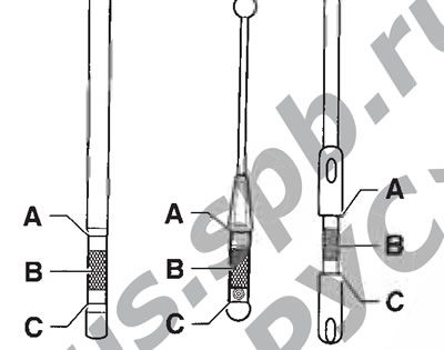
4.8. Markings on the engine oil dipstick
9. To add oil, remove the oil filler cap (2 in the illustrations at the beginning of the chapter). After adding oil, wait a few minutes for the level to stabilize, then check the level again. If necessary, make adjustments again. If dirt is found on the filler cap, wash it with gasoline. Finally, close the oil filler cap tightly.
Note: Do not allow the oil level to be above the "MAX" mark, as this may cause engine damage.
10. Checking the oil level is an important preventive procedure that should be done as often as possible, and definitely before each long trip. In addition, you should pay attention to the condition of the oil: if it is milky or drops of water can be seen in its composition, there may be a leak in the cylinder head gasket or a crack in the cylinder head or block, as a result of which coolant gets into the oil. In this case, the engine should be repaired immediately. If, when rubbing a drop of oil between the thumb and forefinger, you feel particles of dirt or metal particles, the oil should be replaced (see Section 6).
Coolant - checking and adjusting the level and condition
Warning: Do not allow antifreeze to come into contact with your skin or painted surfaces of the vehicle. If this does happen, wash off the antifreeze immediately with plenty of water. Antifreeze is extremely toxic, so do not leave it unattended in an open container or spilled on the floor: children or animals may be attracted by its sweet smell and may drink it.
Caution: Do not remove the expansion tank filler cap or the radiator cap until the engine has completely cooled down!
11. The vehicles in question are equipped with a compensating cooling system with excess pressure. As the engine warms up during operation, the expanding coolant (coolant) fills the tank. When the engine cools down, the coolant automatically flows back into the cooling system, which ensures that the coolant level is maintained at a constant level.
12. The coolant level should be checked regularly, at least every month, and before each long trip.
13. Remove the expansion tank cap (5 in the illustrations at the beginning of the chapter). At room temperature, the coolant level in the expansion tank is considered normal if the coolant reaches the "MIN" indicator and does not go beyond the "MAX" indicator on the wall of the expansion tank. When the engine is warm, the coolant level may temporarily rise above the "MAX" mark. If necessary, add coolant to the expansion tank through its filler neck. Close the cap until you hear a distinct click.
14. To fill the cooling system, always use the mixture of antifreeze and water specified in the Specifications.
Note: If it is necessary to fill the cooling system on the road, then in summer you can use clean water, but not another type of antifreeze. The required type of antifreeze can be added later, but as quickly as possible.
15. If the coolant level drops rapidly, visually inspect the cooling system for leaks: these are usually detected by a white or rust-colored coating in the area surrounding the leak.
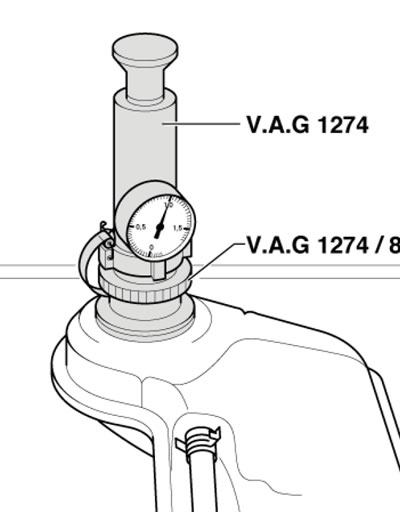
4.15. Checking the tightness of the cooling system (using the M54 engine as an example)
Check the condition of the hoses and the reliability of their fastening to the pipes; replace damaged hoses and clamps (see also Section 5). Cracks are easier to detect if you pinch the hose.
Check the expansion tank cap seal.
Check the cooling system with pressure. To do this, install the VAG1274 pressure build-up device with a hose and a suitable adapter VAG1274/8 on the expansion tank neck (see illustration). Try to create a pressure of about 1 bar using the specified device. If you cannot create such pressure, check the tightness of the cooling system.
16. If no leaks are found, check the expansion tank cap for leaks. To do this, first pull the cap's vacuum valve and release it - it should return to its original position. Make sure that the valve seat is not contaminated or damaged. Then lubricate the cap seal with coolant and connect a pressure-increasing device (see above) with a hose and a suitable adapter to the cap (see illustration). The valve should open at a pressure of approximately 1.4: 1.6 bar. Otherwise, replace the expansion tank cap.
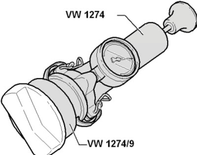
4.16. Checking the expansion tank cap
Note: Coolant residue may cause the safety valve to "suck" to the cover, so to be sure, you should repeat the cover check 2-3 times.
17. You should also check the condition of the coolant - it should be relatively clean. If the liquid is brown or rusty, it should be drained, the cooling system should be flushed and filled with a new mixture (see Chapter 3). Even if the coolant looks normal, the corrosion inhibitors it contains lose their effectiveness over time, so the coolant should be replaced periodically.
18. Use a hydrometer to check the coolant's frost resistance. Use a refractometer to check the proportion of antifreeze.
Washer fluid
19. Windscreen and headlight washer fluid should be added to the appropriate reservoir through the filler neck (6 in the illustrations at the beginning of the chapter).
20. In temperate climates, you can use plain water to wash your windshields, but it is recommended to add a glass cleaner to it. The reservoir should be filled no more than two-thirds full to allow for expansion of the water when it freezes. In cold climates, you should use a special antifreeze washer fluid. It is sold in concentrated or ready-made form.
Caution: Do not use antifreeze for the cooling system as an additive to increase the frost resistance of the washer fluid. Mix concentrated antifreeze washer fluid with water in accordance with the manufacturer's instructions on the packaging.
21. To remove heavy dirt, add a strong detergent to the appropriate tank.
Brake fluid
Caution: Brake fluid may cause damage to your eyes or painted surfaces if it comes into contact with them. Do not use brake fluid that has been open for a long time or that is more than one year old. Brake fluid tends to absorb moisture from the air, which can degrade its properties and lead to a dangerous loss of braking efficiency.
Note: On models with manual transmission, brake fluid is also used to drive the clutch.
22. The brake fluid reservoir is located on the left side of the engine compartment (3 in the illustrations at the beginning of the chapter), and is divided into two parts, each for its own brake circuit. Transparent walls of the reservoir allow the brake fluid level to be observed from the outside. To warn of a low brake fluid level, there is a corresponding K/L in the instrument cluster (see Section 15 Chapters "Controls and operating techniques"). However, it is recommended to check the fluid level regularly.
23. The liquid level with the lid closed should be between the "MIN" and "MAX" marks on the tank wall. Make sure that the level does not fall below the "MIN" mark.
24. If the level is low, first wipe the top of the reservoir and the cap with a clean rag to prevent dirt from getting into the brake system after removing the cap. Add fluid to the correct level, but do not overfill.
25. While the reservoir cap is removed, check the brake fluid and reservoir for contamination. If there are any rust particles, dirt or water droplets, the fluid should be replaced. After bringing the brake fluid level to the correct level, make sure the cap is installed level to prevent fluid leakage and/or dirt ingress.
26. The fluid level in the master cylinder (MC) will drop slightly as a result of wear of the brake pad friction linings. There is no need to top it up as long as the level remains near the "MIN" mark - it will rise after replacing the linings. A very low level may indicate worn brake pads - check them (see Section 9).
27. If the brake fluid level drops constantly, immediately check the entire brake system for leaks. Typically, worn caps in the wheel cylinders are the cause. Inspect the brake lines, hoses and nipples along with the calipers, wheel cylinders and master cylinder (see Section 9). On models with manual transmission, the tightness of the clutch hydraulic lines should also be checked.
28. If, when checking the fluid level, the reservoir is empty or nearly empty, the brake system must be checked for leaks and bled (see Section 9).
Power Steering Fluid
29. The fluid level in the power steering reservoir is measured using a dipstick built into the reservoir cap (7 in the illustrations at the beginning of the chapter). In this case, the engine must be running, and the power steering fluid temperature must be either 20°C or 80°C.
30. The power steering fluid level at 20°C should be in the area of the "MAX" mark on the dipstick, and at a temperature of 80°C - 1 cm higher. Otherwise, add fluid: if the power steering fluid level is significantly lower, check the power steering system for leaks.
Front Differential CVT Transmission Oil
Note: It is not recommended to change the front differential oil during the life of the CVT.
31. Warm up the transmission to approximately 60°C by taking a short drive.
32. Jack up the car so that it is horizontal.
33. Turn off the engine for about 5 minutes to allow the oil to drain into the crankcase.
34. Release the fasteners (2 and 3 in Illustration 5.5 Chapter 2) and remove the rear sound insulation.
35. If there is a bolt (1 in the illustration) on the soundproofing casing above the left drive shaft, unscrew this bolt. Press the lock (2) and remove the casing.
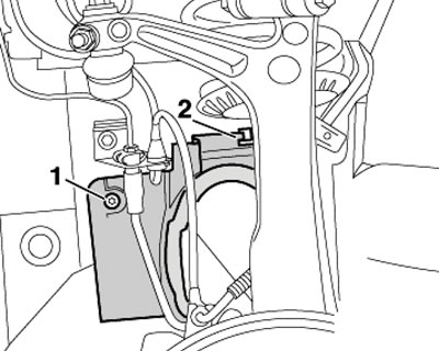
4.35. Fastening the casing above the left drive shaft
36. Unscrew the filler plug (see illustration) and check the oil level by inserting a wire bent at a right angle into the hole. The oil level should be approximately 8.5 mm below the hole. Add oil if necessary.
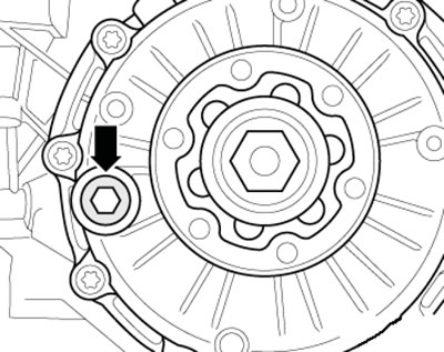
4.36. Front Differential CVT Oil Filler Plug
Note: If you fill the oil until it starts to leak out, you will need to pump out about 200 ml to get the specified level.
37. Tighten the new plug to 20 Nm.
CVT Planetary Transmission Fluid (ATF)
Note: The ATF level is highly dependent on its temperature, and the CVT performance is highly dependent on the ATF level. Therefore, the VAS5051A diagnostic tool should be used to determine the temperature. The VAS5162 tool should be used to add ATF.
38. Make sure that the CVT is not in limp mode.
39. Jack up the car so that it is horizontal.
40. Run the engine at idle speed and make sure that the air conditioning system refrigeration unit is turned off.
41. Connect the VA-S5051A diagnostic tool to the diagnostic connector (see Chapter 5). Make sure the ATF temperature is no more than 30°C. If necessary, allow the transmission to cool down before starting the check.
42. Hang the filling device filled with CVT ATF fluid as high as possible (for example, on the front edge of the open hood).
43. With the engine idling, move the AT selector lever sequentially through all its positions (from "P" to "S"), holding in each of them for about 2 seconds. Return the selector lever to the "P" position.
44. Release the fasteners (2 and 3 in Illustration 5.5 Chapter 2) and remove the rear sound insulation.
45. Install under the filler hole (In the illustration) aTF collection pan and when the ATF temperature reaches 35°C, unscrew the plug of this hole.
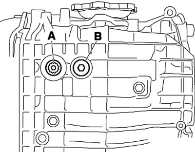
4.45. CVT drain (A) and filler/inspection (B) plugs
Note: When you unscrew the plug, about 50 ml of ATF always flows out of the internal overflow control tube. If the ATF continues to flow out before its temperature reaches 40°C, then its level is OK - tighten the new plug with a force of 20 Nm.
Note: The plug must be tightened when the ATF temperature is no more than 45°C (for moderate climate) or 50°C (for countries with hot climates), otherwise, the amount of ATF leaked due to thermal expansion will be so large that the level of remaining ATF will be insufficient.
46. If ATF starts to leak only at temperatures above 40°C, AT should be added as described below.
47. With the engine idling, screw the nozzle of the VAS5162 tool into the filler hole (see illustration) and turn the tap towards the receiving tube - ATF will start flowing into the CVT.
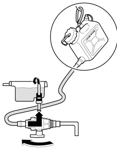
4.47. Refueling CVT
48. After some time, check the ATF level by turning the tap towards the outlet pipe of the device: the ATF level is normal if only a small amount of ATF flows out of the outlet pipe at a temperature of less than 45°C.
Note: Approximately 50 ml of ATF that flows out each time the outlet pipe is opened is not counted. If no more than 50 ml of ATF flows out, turn the tap toward the feed pipe and check again after a while.
49. After receiving a positive test result, tighten the new plug with a torque of 20 Nm.
Note: The plug must be tightened when the ATF temperature is no more than 45°C (for moderate climate) or 50°C (for countries with hot climates), otherwise, the amount of ATF leaked due to thermal expansion will be so large that the level of remaining ATF will be insufficient.
Transmission oil for front differential and transfer case of models with automatic transmission
50. The check is carried out at an oil temperature of about 20°C.
51. Jack up the car so that it is horizontal.
52. Unscrew the filler plug (see illustration) and check the oil level by inserting a wire bent at a right angle into the hole. The oil level should reach the bottom edge of this hole. Add oil if necessary.
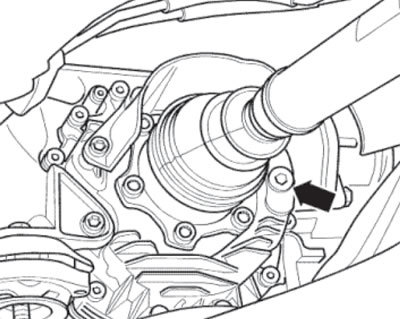
4.52a. Front differential filler plug AT
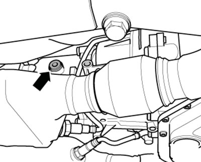
4.52b. Transfer case filler plug AT
53. Tighten the new plug to 35 Nm.
AT Planetary Transmission Fluid (ATF)
Note: The ATF level is highly dependent on its temperature, and the AT performance is highly dependent on the ATF level. Therefore, the VAS5051A diagnostic tool should be used to determine the temperature. The VAS1924 tool should be used to add ATF.
54. Perform the actions described in paragraphs 38-43.
55. Install under the filler hole (In the illustration) aTF collection pan and when the ATF temperature reaches 35°C, unscrew the plug of this hole.
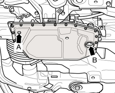
4.55. Plugs of drain (A) and inspection and fill (B) holes of AT
Note: When unscrewing the plug, approximately 50 ml of ATF always flows out of the internal overflow control tube. If the ATF continues to flow out before its temperature reaches 40°C, then its level is OK - tighten the plug with a new sealing ring to 80 Nm.
Note: The plug must be tightened when the ATF temperature is no more than 45°C (for moderate climate) or 50°C (for countries with hot climates), otherwise, the amount of ATF leaked due to thermal expansion will be so large that the level of remaining ATF will be insufficient.
56. If ATF starts to leak only at temperatures above 40°C, AT should be added as described below.
57. With the engine idling, screw the nozzle of the VAS1924 tool into the filler hole (see illustration). Do not push the protective mushroom plug upwards. Let the fluid flow from the filling device into the AT and check the AT level again. Add more ATF if necessary.
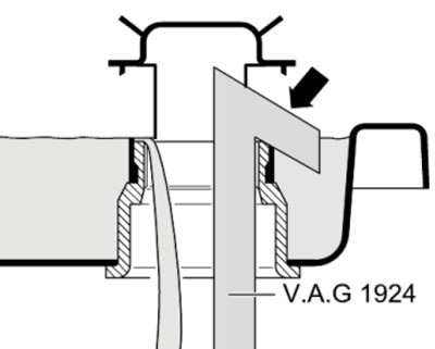
4.57. Refueling AT
Transmission oil for manual transmission and rear differential
58. Jack up the car so that it is horizontal.
59. Unscrew the filler plug (see illustrations) and check the oil level by inserting a wire bent at a right angle into the hole. In the case of a rear differential, the oil level should reach the lower edge of this hole, and in the case of a manual transmission, the oil level should be approximately 4±1 mm below the hole. Add oil if necessary.
60. Tighten the new plug to the required torque (see Specifications).