
Repair Chevrolet Repair Toyota Repair Honda Repair AvtoVAZ Repair Mercedes-Benz Repair BMW Repair Opel
Home  |  Contacts  |  Sitemap  |    
English Русский
Български
Беларускі
Український
Српски
Hrvatski
Română
Polski
Slovenský
Magyar
AudiManual.ru


  • AUDI 80
  • AUDI 100
  • AUDI A3
  • AUDI A4
  • AUDI A6
  • AUDI A8
  • AUDI Q
  • OTHER
  • ARTICLES
B8 (2007-2015) B7 (2004-2008) B6 (2000-2006) B6 (2000-2006, petrol) B5 (1994-2001) B5 (1994-2001, petrol)

General information and safety precautions (Audi A4 B7)

  • Home
  • Audi A4
  • B7 (2004-2008)
  • Chassis
  • Brake system
  • General information and safety precautions
            0
Table of contents: General information ↓ Security measures ↓

General information


All wheels of the vehicles considered in this Manual are equipped with disc brakes. The front brake discs are ventilated. Depending on the configuration, brake mechanisms of different models can be installed. The main components of the installation and assembly of brake mechanisms are shown in illustrations 1.1ad.

1.1a. Front brake mechanism installation details FN3 1. Brake mechanism shield; 2. Flange bolt…

1.1a. Front brake mechanism installation details FN3 1. Brake mechanism shield; 2. Flange bolt M6x12, 10 Nm; 3. Brake hose; 4. Bracket; 5. Bolt, 10 Nm; 6. Spring lock; 7. Brake pipe; 8. Connector; 9. Knurled bolt, 190 Nm; 10. Anchor bracket; 11. Brake pads; 12. Retaining spring; 13. Brake disc; 14. Bolt, 5 Nm; 15. Support; 16. Guide pin, 30 Nm; 17. Protective cap
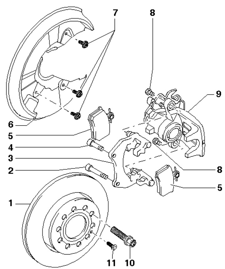

1.1b. Rear brake mechanism installation details C38 1. Brake disc; 2. Knurled bolt M10x1.25x60, 75…

1.1b. Rear brake mechanism installation details C38 1. Brake disc; 2. Knurled bolt M10x1.25x60, 75 Nm, subject to replacement; 3. Anchor bracket with guide pins and protective caps; 4. Knurled bolt M10x1.25x50, 75 Nm, subject to replacement; 5. Brake pads; 6. Brake mechanism shield; 7. Flange bolt M6x12, 10 Nm; 8. Self-locking bolt, 35 Nm, must be replaced; 9. Support; 10. Wheel bolts; 11. Bolt, 5 Nm
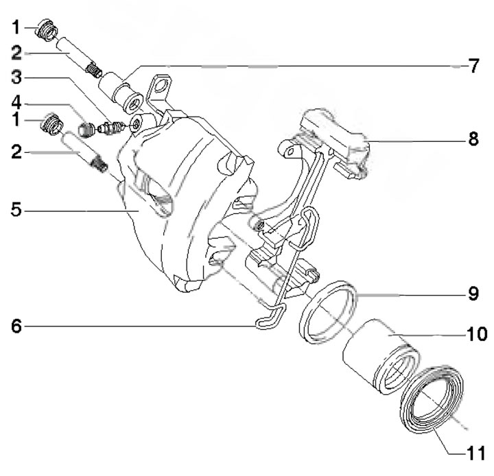


1.1c. Front Brake Assembly Details FN3 1. Protective caps; 2. Guide pins, 30 Nm; 3. Bleed nipple,…

1.1c. Front Brake Assembly Details FN3 1. Protective caps; 2. Guide pins, 30 Nm; 3. Bleed nipple, 10 Nm; 4. Cap of nipple 3; 5. Support; 6. Retaining spring; 7. Bearing bushing; 8. Anchor bracket; 9. Cuff; 10. Piston; 11. Protective cap
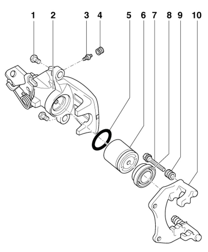

1.1d. Front brake assembly parts C38 1. Self-locking bolt, 35 Nm, must be replaced; 2. Caliper with…

1.1d. Front brake assembly parts C38 1. Self-locking bolt, 35 Nm, must be replaced; 2. Caliper with lever for parking brake cable; 3. Bleed nipple; 4. Cap of nipple 3; 5. Cuff; 6. Piston with automatic adjustment; 7. Guide pin; 8. Protective cap; 9. Protective caps; 10. Anchor bracket with guide pins and protective caps


The brake system is divided diagonally into two independent hydraulic circuits and consists of a master brake cylinder (MBC) with a vacuum booster (see illustration 1.2) and brake mechanisms. If one of the circuits fails, (for example, as a result of a breach in the seal) the second continues to function in normal mode, providing adequate braking of the car. The fluid pressure in both circuits is created by a tandem-design master brake cylinder (MBC). The MBC is activated when the brake pedal is depressed (see illustration 1.3).
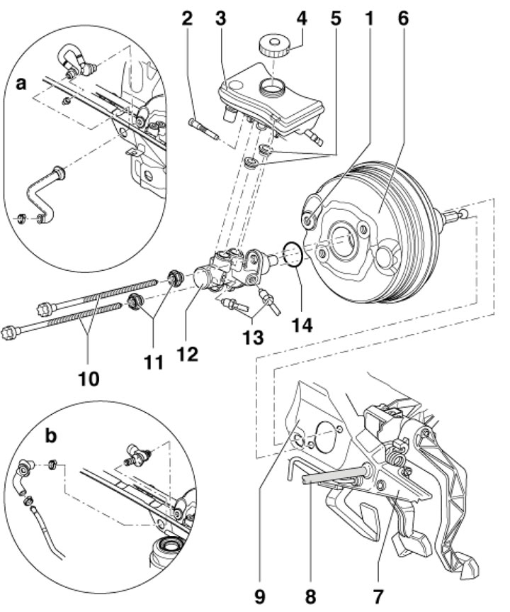


1.2. Master cylinder and vacuum booster 1a, b. Vacuum hose connection; 2. Reservoir axle bolt 3.8…

1.2. Master cylinder and vacuum booster 1a, b. Vacuum hose connection; 2. Reservoir axle bolt 3.8 Nm; 3. Brake fluid reservoir with low fluid level D/V; 4. Tank cover 3; 5. Cuffs; 6. Vacuum booster; 7. Pedal bracket; 8. Feed hose; 9. Engine compartment overhaul; 10. Bolt, 25 Nm; 11. Flange nut, 50 Nm, subject to replacement; 12. GTZ; 13. Brake pipes, 15 Nm; 14. Sealing ring
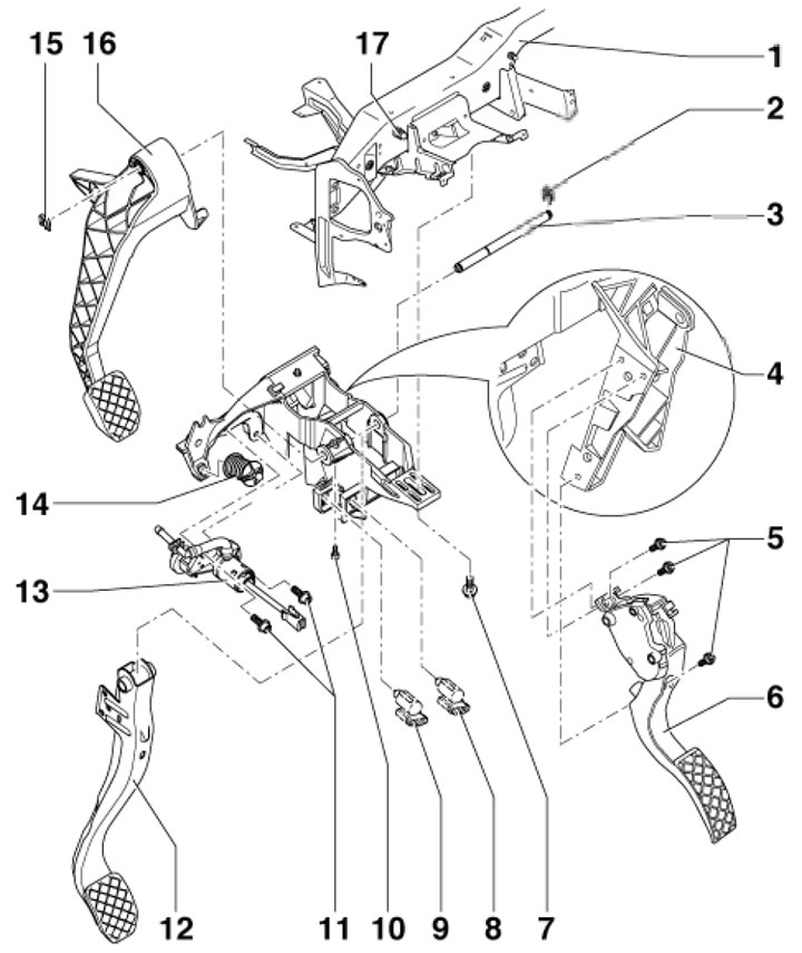

1.3. Pedal assembly parts 1. Instrument panel crossbar; 2. The fasteners are subject to…

1.3. Pedal assembly parts 1. Instrument panel crossbar; 2. The fasteners are subject to replacement; 3. Brake and clutch pedal axle; 4. Bracket; 5. Bolt, 10 Nm; 6. Accelerator pedal module; 7. with washer, 25 Nm; 8. D/W brake lights; 9. D/B position of the clutch pedal; 10. Bolts, 5 Nm; 11. Bolt with washer, 20 Nm; 12. Brake pedal; 13. GTZ; 14. Spring (white - for the brake pedal, black - for the clutch pedal); 15. Holder; 16. Clutch pedal; 17. Hairpin


The brake fluid reservoir is fixed to the master cylinder. The brake booster accumulates part of the vacuum created in the engine intake manifold. Diesel engines normally have no vacuum in the intake manifold, so a vacuum pump is used on diesel models to ensure sufficient vacuum supply. On models with AT or CVT, an electric vacuum pump is additionally used.

The parking brake is controlled by a lever, the movement of which through cables acts on the shoes of the rear brake mechanisms. The ABS system is installed as standard, which can be supplemented with auxiliary functions. The main components of the ABS and ESP systems are shown in Figures 1.4a-c.
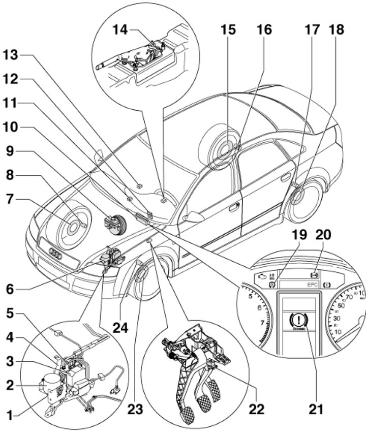
1.4a. ABS/ESP system parts 1. Hydromodulator holder; 2. Brake booster vacuum pump; 3. ABS control…

1.4a. ABS/ESP system parts 1. Hydromodulator holder; 2. Brake booster vacuum pump; 3. ABS control unit; 4. Hydromodulator; 5. Sensor 1 of pressure in the brake system; 6. Assembly of the hydraulic modulator and the electronic control unit ABS/ESP; 7. Sensor rotor 8; 8. Front right wheel sensor; 9. D/V low brake fluid level; 10. Instrument panel insert; 11. ESP switch; 12. Steering wheel angle sensor; 13. Yaw rate and lateral acceleration sensor; 14. D/V of the cocked parking brake lever; 15. Sensor rotor 16; 16. Rear right wheel sensor; 17. Rear left wheel sensor; 18. Sensor rotor 17; 19. K/L ESP; 20. K/L ABS; 21. K/L brake system; 22. D/W brake lights; 23. Sensor rotor 24; 24. Front left wheel sensor
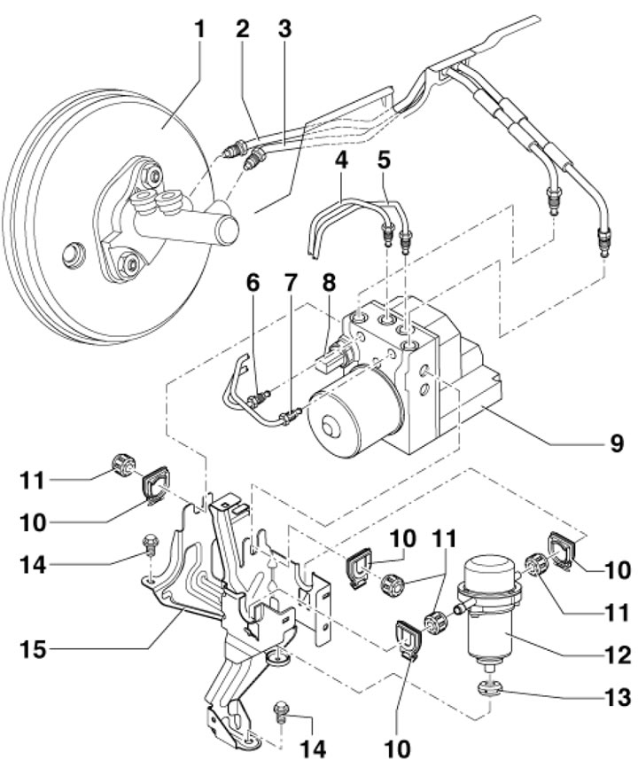


1.4b. Bosch 5.7 hydraulic modulator and control unit assembly parts 1. Vacuum booster and master…

1.4b. Bosch 5.7 hydraulic modulator and control unit assembly parts 1. Vacuum booster and master cylinder; 2. Brake pipe: Master cylinder/primary piston circuit to hydraulic modulator, 20 Nm; 3. Brake pipe: Master cylinder/secondary piston circuit to hydraulic modulator, 20 Nm; 4/5. Brake pipe: hydraulic modulator to front left/right caliper, 12 Nm; 6/7. Brake pipe: hydraulic modulator to rear right/left caliper, 12 Nm; 8. Brake pressure sensor, 12 Nm; 9. Hydraulic modulator with ABS control unit; 10. Retainer; 11, 13. Buffers; 12. Vacuum pump; 14. Bolts, 3 pcs., 10 Nm; 15. Bracket
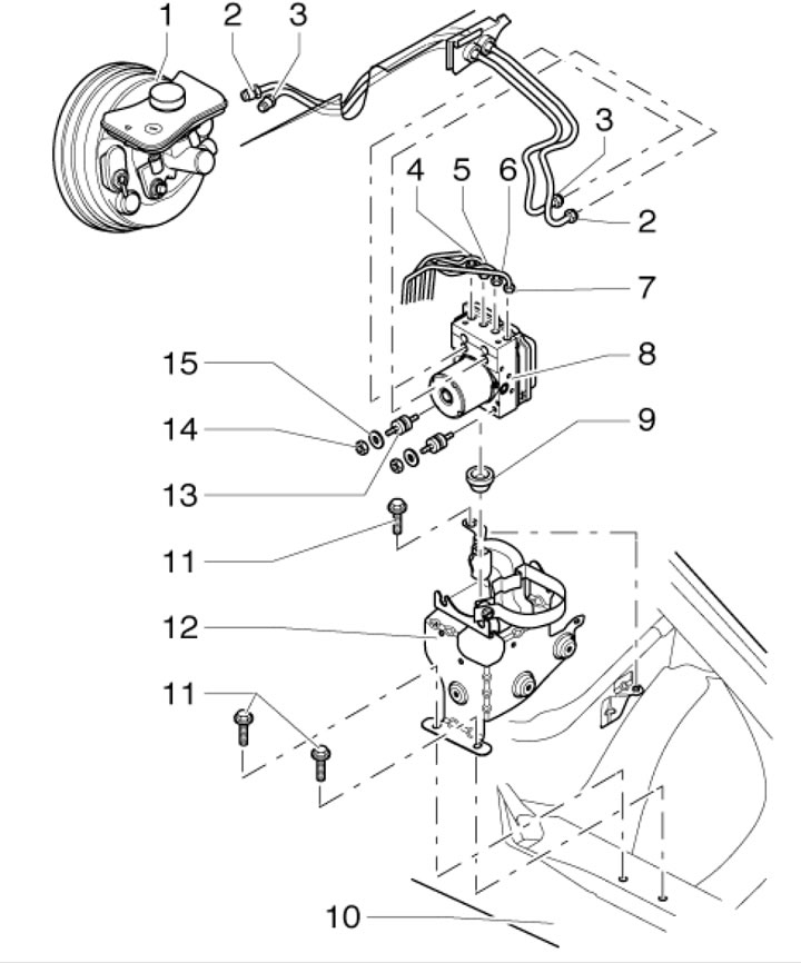

1.4a. ABS/ESP system parts 1. Hydromodulator holder; 2. Brake booster vacuum pump; 3. ABS control…

1.4a. ABS/ESP system parts 1. Hydromodulator holder; 2. Brake booster vacuum pump; 3. ABS control unit; 4. Hydromodulator; 5. Sensor 1 of pressure in the brake system; 6. Assembly of the hydraulic modulator and the electronic control unit ABS/ESP; 7. Sensor rotor 8; 8. Front right wheel sensor; 9. D/V low brake fluid level; 10. Instrument panel insert; 11. ESP switch; 12. Steering wheel angle sensor; 13. Yaw rate and lateral acceleration sensor; 14. D/V of the cocked parking brake lever; 15. Sensor rotor 16; 16. Rear right wheel sensor; 17. Rear left wheel sensor; 18. Sensor rotor 17; 19. K/L ESP; 20. K/L ABS; 21. K/L brake system; 22. D/W brake lights; 23. Sensor rotor 24; 24. Front left wheel sensor


Bleeding and checking the brake system, as well as replacing the brake fluid, are described in Sections 8 and 9 of Chapter 1.

Security measures


Brake fluid is a highly toxic and chemically aggressive compound and when in contact with body panels it destroys the paintwork.

The dust generated during the wear of brake pads may contain asbestos, which is harmful to human health - do not inhale it under any circumstances when cleaning the brake mechanisms!

Working with the brake system requires special cleanliness and strict adherence to instructions. If you do not have the necessary experience, it is advisable to contact a service station.

Note: When driving on wet roads, periodically press the brake pedal to remove moisture from the brake discs; During the rotation of the wheel, moisture is thrown off the brake discs under the action of centrifugal force, but a film of silicone, rubber abrasion products, grease and other contaminants remain, reducing braking efficiency!


Corroded disc brakes create a shaking effect when braking, which does not disappear over time. In this case, the discs should be replaced.

The burning of dirt onto the surface of the brake pads leads to the formation of grooves on the surface of the brake discs, which leads to a decrease in braking efficiency.

(The original publication in its entirety is posted on the website: AUDImanual.ru)
The article was checked by auto expert Timur Bazhenov
This article is available at russian, bulgarian, belarusian, ukrainian, serbian, croatian, romanian, polish, slovak, hungarian

Share information:
Previous articles
Audi A4 B7: Brake system
Next articles

Brake system — specifications
Replacing brake pads and their sensors
Removal and installation parking brake cables
Removal and installation the parking brake lever, returning it…
Adjusting the parking brake drive


Similar articles on other Audi car models:
Vehicle traffic safety Audi 80 B3 (1986-1991, petrol)
Safety precautions when working with the ignition system Audi 100 C4 (1990-1994, petrol)
Safety precautions to avoid damage to the catalytic converter Audi A3 Type 8L (1996-2003)
Description of electrical equipment and safety precautions Audi A6 C4 (1994-1997)
Safety requirements and warnings Audi A8 D2 (1994-2002)
General information and safety precautions: power supply system Audi Q7 Typ 4L (2005-2015, diesel)
Safety precautions when working with the fuel supply system Audi A2 (1999-2005)
Link to this page in different formats


Visitor comments

No comments yet


How much will 33 + 21 =


A4(B8, 2007-2015) 
  • General information
  • Operating instructions
  • Power unit
  • Petrol engines 1.8 l
  • Petrol engines 1.8/2.0 l
  • Petrol engines 3.0 l
  • Petrol engines 3.2 l
  • Fuel system (petrol)
  • Diesel engines 2.0 l (CA*)
  • Diesel engines 2.0 l (CJCB)
  • Diesel engines 2.7/3.0 l
  • Diesel engines 3.0 l
  • Fuel system (diesel)
  • Transmission
  • Manual gearbox 0B1
  • Manual gearbox 0B2
  • Manual gearbox 0B3
  • Manual gearbox 0B4
  • Automatic transmission 0B5
  • Automatic transmission 0B6
  • Automatic transmission 0AW
  • All-wheel drive system
  • Chassis
  • Front suspension
  • Rear suspension
  • Brake system
  • Steering system
  • Body
  • Exterior
  • Interior
  • Seats
  • Doors, locks and windows
  • Security system
  • Heating and air conditioning
  • Electrical equipment
  • Audio system
  • Power devices
  • Equipment and devices
  • Lighting and lamps
  • Electrical circuits
 
A4(B7, 2004-2008) 
  • General information
  • Introduction to manual
  • Troubleshooting
  • Operating instructions
  • Maintenance
  • Power unit
  • Petrol engines 2.0 (ALT)
  • Petrol engines 2.0 (TFSI)
  • Petrol engines 1.8 (MPI)
  • Diesel engines
  • Cooling system
  • Air conditioner
  • Fuel and exhaust system
  • Ignition system
  • Starting and charging
  • Transmission
  • Clutch
  • Manual gearbox
  • Automatic gearbox
  • Drive shafts
  • Chassis
  • Brake system
  • Front suspension
  • Rear suspension
  • Steering
  • Body
  • Exterior
  • Interior
  • Electrical equipment
  • Equipment and devices
  • Lighting and signaling
  • Windscreen wipers and washers
  • Electrical diagrams
  • Electrical diagrams (since 2007)
 
A4(B6, 2000-2006) 
  • General information
  • Vehicle Description
  • User manual
  • Maintenance
  • Power unit
  • Gasoline engine
  • Diesel engine
  • Lubrication system
  • Cooling system
  • Supply system
  • Injection system
  • Exhaust system
  • Ignition and control
  • Transmission
  • Gear box
  • Clutch and drive shafts
  • Chassis
  • Brake system
  • Car suspension
  • Steering
  • Body
  • Heating and ventilation
  • Exterior (external elements)
  • Interior (internal elements)
  • Electrical equipment
  • Power devices
  • Lighting and appliances
  • Electrical circuits
 
A4(B6, 2000-2006, petrol) 
  • General information
  • Introduction to the guide
  • Car care
  • Power unit
  • Engine repair
  • Lubrication system
  • Cooling system
  • Injection and control system
  • Ignition system
  • Power and exhaust system
  • Transmission
  • Clutch and drive shafts
  • Car gearbox
  • Chassis
  • Suspension and wheels
  • Steering
  • Brake system
  • Body
  • Interior
  • Exterior
  • Electrical equipment
  • Equipment and devices
  • Lighting and signaling
  • Power devices
  • Electrical circuits
 
A4(B5, 1994-2001) 
  • General information
  • Introduction to the guide
  • Car care
  • Maintenance (gasoline)
  • Maintenance (diesel)
  • Power unit
  • Gasoline engines
  • Diesel engines
  • Engine overhaul
  • Cooling system
  • Fuel injection (gasoline)
  • Fuel system (diesel)
  • Exhaust system
  • Ignition system
  • Transmission
  • Clutch
  • Mechanical gearbox
  • Automatic gearbox
  • Drive shafts
  • Chassis
  • Brake system
  • Car suspension
  • Steering
  • Body
  • Exterior
  • Interior
  • Doors, locks and windows
  • Heating and ventilation
  • Electrical equipment
  • Power devices
  • Equipment and devices
  • Electrical circuits
 
A4(B5, 1994-2001, petrol) 
  • General information
  • Vehicle description
  • Maintenance
  • Power unit
  • Engine repair
  • Turbocharging
  • Exhaust system
  • Cooling system
  • Ignition system
  • Fuel system
  • Motronic injection system
  • MPI and MPFI injection system
  • Transmission
  • Clutch
  • Gearbox and shafts
  • Chassis
  • Steering
  • Car suspension
  • Brake system
  • Wheels and tires
  • Body
  • Heating and ventilation
  • Body parts
  • Electrical equipment
  • Fuses and relays
  • Power devices
  • Lighting and lamps
  • Tools and devices
  • Electrical circuits
 
AudiManual.ru © 2017-2026 · Mobile version · Feedback · Sitemap: EN BG BY UA RS HR RO PL SK HU · Site search · News and articles
80 B2 · 80 B3 petrol · 80 B3 · 80 B4 · 100 C3 diesel · 100 C3 petrol · 100 C3 · 100 C4 petrol · 100 C4 · A3 Type 8L · A4 B5 petrol · A4 B5 · A4 B6 petrol · A4 B6 · A4 B7 · A4 B8 · A6 C4 · A6 C5 · A6 C5 Allroad · A8 D2 · Q5 Type 8R · Q7 Typ 4L · Audi A2 ·
This site uses cookies 🍪. Click the button to accept this fact.