



Table of contents: On-Board Diagnostics (OBD) System ↓ Information about diagnostic devices ↓
On-Board Diagnostics (OBD) System
1. The models described in this Manual are equipped with a second-generation on-board diagnostics system (OBD II).
2. Reading data from the OBD II system and clearing its memory is performed using special diagnostic equipment connected to the diagnostic connector (DLC, see illustration). It would be reasonable to entrust the procedures for reading DTC codes and clearing the ECM memory to service station specialists.
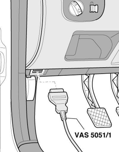
4.2. Connecting the VAS5051 scanner to the diagnostic connector via the VAS5051/1 cable
Information about diagnostic devices
3. Checking the proper functioning of the injection system components and reducing exhaust toxicity is performed using a universal digital meter (multimeter). Using a digital meter is preferable for several reasons. Firstly, it is quite difficult to measure the value of an analog meter (sometimes - impossible), determine the result of the reading with an accuracy of hundredths and thousandths, while when examining circuits that include electronic components, such accuracy acquires special significance. The second, no less important, reason is the fact that the internal circuit of the digital multimeter has a fairly high impedance. Since the voltmeter is connected to the circuit being tested in parallel, the accuracy of the measurement is higher, the less current passes through the device itself. This factor is not significant when measuring relatively high voltage values (9:12 V), but becomes decisive when diagnosing elements that produce low-voltage signals, such as, for example, a lambda probe, where we are talking about measuring fractions of a volt.
4. Parallel monitoring of signal parameters, resistances and voltages in all control circuits is possible using a splitter connected in series to the engine control unit connector. In this case, with the engine off or running, or while the car is moving, the signal parameters are measured at the terminals of the splitter, from which a conclusion is made about possible defects.
5. Special diagnostic scanners or testers with a specific cartridge can be used to diagnose electronic systems of a car (if provided), universal cable and connector. In addition, for this purpose, you can use a specialized automotive diagnostic computer, specially designed for complete diagnostics of most systems of modern cars (for example, ADC2000 from Launch HiTech). Also, for this purpose, you can use scanners and specialized diagnostic analyzers, for example, FDS 2000, Bosch FSA 560 or a regular personal computer with a special adapter, cable and an installed OBD II browser program.
6. Audi recommends using the VAS5051 diagnostic system.
7. Some scanners, in addition to the usual diagnostic operations, allow, when connected to a personal computer, to print out the basic diagrams of electrical equipment stored in the control unit memory (if any are included), program the anti-theft system, monitor signals in the car circuits in real time.
(The original article is posted on the resource: AudiManual)