
Table of contents: Checking for the presence of… ↓ Visual inspection of the ignition… ↓ Causes of malfunctions ↓ Checking the ignition coil. Models… ↓ Checking the Electronic Switch.… ↓ High voltage transformer ↓ Checking the high voltage transformer ↓ Checking the ignition coils. Models… ↓ Checking the Electronic Switch.… ↓ Checking the Hall Sensor. Models… ↓ Checking the Hall Sensor. Models… ↓ Checking the Crankshaft Speed… ↓ Checking the ignition timing sensor.… ↓ Checking the control unit ↓
Anyone who wants to find a fault in the ignition system must act according to the system.
A simple secondary voltage test can be used to determine whether an igniting spark is being produced at all.
The power supply for the ignition and injection systems passes through thermal fuses in the brown, black and red holders (in the ignition system block). If the ignition system fails, these fuses should be checked (chapter "Body electrical system").
A precise visual inspection of the ignition system helps to detect the most common causes of failures (faulty wires and plugs, electrical breakdowns).
Only now should you check the ignition coil, Hall sensor or speed sensor or ignition timing sensor one by one.
If all this does not lead to success, you need to query the fault memory (in the workshop).
Checking for the presence of secondary voltage
First of all, we check whether the ignition system provides an igniting spark:
Disconnect the high-voltage wire from the spark plug and unscrew the spark plug.
Put the wire back on the spark plug and place it on the cylinder block so that it has reliable contact with the "ground" (housing). Even better - create an electrical circuit by connecting the spark plug thread to the engine using an auxiliary cable for "lighting".
Have an assistant crank the engine with the starter.
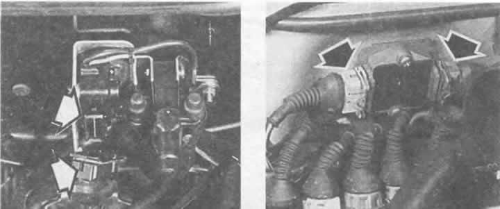
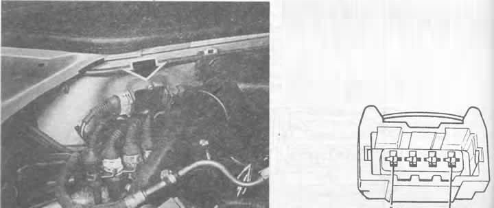
"Disabling" the ignition by disconnecting the plugs (arrows) on the electronic switches of the ignition coils, on the left using the example of models with 4- and 5-cylinder engines, on the right using the example of a 6-cylinder engine.
The illustration shows the ignition coil pack of 6-cylinder engines with the engine protection removed. The numbers on the high-voltage connectors indicate which wire should be connected to which cylinder.
Checking the ignition system for sparking. For safety reasons, the spark plug should be electrically connected to the engine via an auxiliary cable, which is not shown here.
If there is a powerful spark overlap on the spark plug electrode, then there is current in the ignition system. The main ignition adjustment may be incorrectly set (see the relevant section in this chapter).
If there is no spark, repeat the test with the spark plug of another cylinder. If there is no spark there either, the entire ignition system should be checked.
Visual inspection of the ignition system
Are all terminals and plug contacts firmly secured on the ignition coil, electronic ignition control unit or ignition and injection control unit and on the ignition distributor?
Is there a loose contact in the multi-pin plug?
Is the ignition coil leaking filler material? In this case, it is probably faulty
Are there any cracks or traces of carbon deposits from spark breakdowns on the ignition coil housing?
Additionally, check whether the main cables and high-voltage wires are securely soldered and whether their insulation is intact.
Is there any damage to the distributor cap?
Are all ignition system components clean and dry? Dirt can cause electrical breakdowns.
Hint: connect and disconnect control devices only when the ignition is off.
In addition to complete failure of the ignition system due to lack of power, too low voltage can also cause serious malfunctions!
Is the ignition system power supply ok?
Are the fuses ok?
4- and 5-cylinder models: Disconnect the connectors at the electronic switch near the ignition coil.
Connect the measuring device to the disconnected plug between contact 1 (terminal 15) and contact 3 (ground).
Turn on the ignition.
The voltmeter should show at least 11.5 V.
If the device does not show any voltage at all or shows too little voltage, then the problem is in the wiring to the ignition switch.
The same can be said about the plug in a car equipped with a so-called high voltage transformer.
Models with 4-cylinder engines: perform the same measurement on the black-blue wire of the Motronic or Digifant control unit.
Models with 5-cylinder engine: perform the same measurement at the black/blue wire of the fully electronic ignition system control unit.
And in these places the indicator should be at least 11.5 V.
Models with 6-cylinder engine: Disconnect the white plug connection at the rear wall of the engine compartment (supplying power to ignition coils), connect a measuring device between each of the three terminal 15 connectors at the top of the plug connection and ground.
Turn on the ignition.
Each measurement should show at least 11.5 V.
If the device does not show any voltage at all or shows too little voltage, then the problem is in the wiring to the ignition switch.
Perform the same measurement on the black-green cable of the MPI/MPFI system control unit.
The reading should be at least 11.5 V.
Causes of malfunctions
Prerequisite: the battery is charged, the fuses are in order.
The ignition switch is faulty (chapter "Instruments and auxiliary devices").
Break in wiring between ignition switch and central switch and between central switch and ignition coil or between central switch and control unit. Check wiring and plugs based on wiring diagrams in the book.
Checking the ignition coil. Models with 4- and 5-cylinder engines
A visual inspection of the ignition coil has already been performed.
To check the resistance with the ignition off, disconnect all wires from the ignition coil. We measure the primary and secondary windings.
Measure the resistance between the ignition coil terminals 1/- and 15/+ using an accurate ohmmeter.
Standard resistance: 0.5-1.5 Ohm.
The next measurement is between terminals 1/- and 4.
Here the ohmmeter should show 5-9 kOhm.
If the above indicators are not achieved, the ignition coil should be replaced.
These measurements cannot detect a short circuit between the windings. Therefore, if despite the good results obtained, you still believe that the ignition coil is the cause of the problem, you must take the removed ignition coil to an auto electrical system workshop for rechecking.
Checking the Electronic Switch. Models with 4- and 5-Cylinder Engines
It is impossible to check the functionality of only one electronic switch located next to the ignition coil. Therefore, you should proceed as follows:
Checking the controls: Disconnect the plugs on the electronic switch next to the ignition coil.
Connect the voltmeter to the connectors between pin 2 (control) and contact 3 ("ground").
Turn the engine over with the starter.
The voltmeter should show at least 2V.
Check the power supply to the ignition system using the diagram already described.
Check the ignition coil, see next section.
If there is no spark in the ignition system, despite the fact that the three mentioned checks did not reveal any faults, then the electronic switch is defective. In this case, the electronic switch must be replaced together with the ignition coil.
High voltage transformer
In some 4-cylinder models, the ignition coil and electronic switch are combined into one unit (high voltage transformer). Connections from terminals 1 and 15 of the ignition coil are located under the protective cover. The connection to the "ground" (housing) passes directly through the housing. The mode of action corresponds to the ignition coil with an electronic switch.
Checking the high voltage transformer
Visual inspection has already been carried out.
To check the resistance with the ignition off, disconnect the three-pin plug and the main high-voltage wire of the transformer. We measure the primary and secondary winding of the element with the coil.
Measure the resistance between the high voltage transformer terminals 1/- and 15/+.
Standard value: 0.5-0.7 Ohm.
The next measurement is between terminals 15 and 4.
Standard values: 3-4 kOhm.
If the specified values are not achieved, the transformer should be replaced.
These measurements cannot detect a short circuit between the windings. Therefore, you still consider the high-voltage transformer to be the cause of the malfunction, you need to give the removed transformer to an auto electrical system workshop for rechecking.
To check the voltage you will need a voltmeter, as well as auxiliary cables with test leads.
Connect the measuring cable to both outer contacts of the three-pin plug of the high voltage transformer.
Turn on the ignition, the voltmeter should show approximately 12 V. If there is no voltage, you need to look for a break in the cable in the positive or negative wiring.
Turn off the ignition.
The photo shows the ignition coil for 4 and 5 cylinder models with the correct terminal markings.
The figure shows the arrangement of the contacts of the connecting plug at the electronic switch (important for checks).
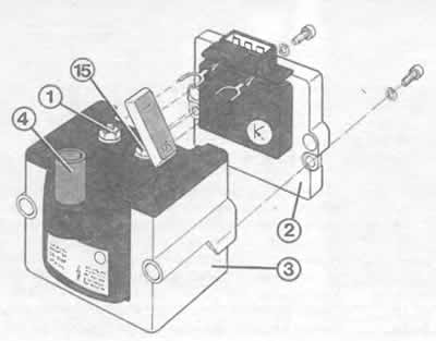
Some models with 4-cylinder engines are equipped with similar high-voltage transformers. The ignition coil (3) and the electronic switch (2) are combined here in a single housing. In this case, the connections are also marked with the corresponding terminal designations, with terminals 1 and 15 only accessible after opening a small cover. The illustration also shows a three-pin plug.
Pulse check: fuse #17 in the fuse box to prevent fuel from being injected unnecessarily.
Connect the LED voltmeter via auxiliary cables and test leads to contacts 2 and 3 of the transformer plug.
Ask an assistant to bring the starter.
The LEDs should flicker. If not, then the problem is in the Hall sensor or the Mono-Motronic or Digifant injection system control unit is faulty.
Turn off the ignition.
Checking the ignition coils. Models with 6-cylinder engines
A visual inspection of the ignition coils has already been performed.
To check the resistance, disconnect all high-voltage wires from the ignition coils. Check the secondary winding of the coils.
Measure the resistance between the high-voltage wire sockets of the ignition system of the first and sixth cylinders with an accurate ohmmeter (first coil).
Standard value: 9-14 kOhm.
The same measurement should be made between the high-voltage wire sockets of the second and fourth cylinders, as well as the wire sockets of the third and fifth cylinders (second and third coils).
If everything is OK, the next step is to check the secondary winding of the coils.
Disconnect the white plug connection near the rear wall of the engine compartment (ignition coil power supply), connect the measuring device of your choice to one of the three contacts of terminal 15 at the top of the plug connection.
Disconnect the three-pole plug of the electronic switch (also near the rear wall of the engine compartment), connect the second wire of the ohmmeter in turn to all three terminals in the plug.
Standard value: 0.5-1.0 Ohm should be obtained in all three measurements.
If this is not the case, the ignition coil pack should be replaced.
Checking the Electronic Switch. Models with 6-Cylinder Engine
Remove the plugs from all six injection nozzles.
Disconnect the 4-pin plug of the electronic switch (near the rear wall of the engine compartment).
Connect the LED voltmeter to ground.
Connect the free wire of the voltmeter in turn to contacts 1, 3 and 4 of the disconnected plug.
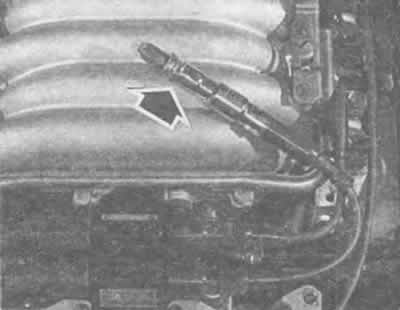
The electronic switch (arrow) of the ignition coils of the 6-cylinder engine is located at the rear wall of the engine compartment. The figure shows the arrangement of the contacts of the 4-pin plug. The arrangement of the contacts of the 3-pin plug corresponds to that shown in the figure on the previous page (4- and 5-cylinder engines).
Each time, the assistant turns the engine with the starter.
The LED voltmeter should flash for all three measurements, otherwise the control should be checked or the electronic switch should be replaced.
Checking the Hall Sensor. Models with 4- and 5-cylinder engines
Disconnect the electronic switch connectors near the ignition coil.
Pull off the rubber cap of the Hall sensor plug (on the side of the ignition distributor) with the plug connected - so that the plug contacts become accessible.
Connect the voltmeter to terminal 2 (purple wire) and 3 (purple-brown wire) plugs.
Turn on the ignition and slowly turn the engine by hand so that the perforated diaphragm (trigger) of the distributor rotates, enters the Hall sensor and exits it.
Monitor the meter: it should show 0-0.5 V if the diaphragm is outside the Hall sensor. When the diaphragm is inside the Hall sensor, the reading should be at least 4 V.
If there are no pulses, then you should check the power supply of the Hall sensor:
Disconnect the plugs from the distributor and connect a voltmeter to both outer contacts of the plug.
Turn on the ignition, the voltmeter should now show at least 9 V.
Otherwise, the control unit/wiring is faulty.
Checking the Hall Sensor. Models with 6-Cylinder Engine
Disconnect all injection nozzle connectors.
Pull off the rubber cap of the plug behind the Hall sensor (the plug remains connected).
Check with an LED voltmeter for voltage between terminals 1 and 3 of the plug when the ignition is on (the terminals on the plug are marked).
Otherwise, check the wiring.
Connect the LED voltmeter between terminals 2 and 3.
Ask an assistant to turn the engine over with the starter.
The LED voltmeter should flash, in which case the Hall sensor is OK.
Hint: if the Hall sensor is faulty, it is not necessary to change the entire distributor. The Hall sensor can be purchased separately.
Checking the Crankshaft Speed Sensor. Models with 6-Cylinder Engines
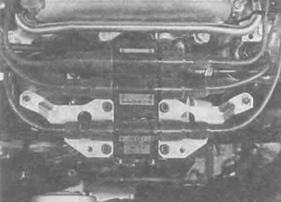
The RPM sensor is located above the flywheel ring gear. Its plug connection points upwards to the plug holder on the rear wall of the engine compartment, so there is no need to take measurements under the car.
Check the wire from the sensor to the holder on the rear wall of the engine compartment, check the reliability of the plug connection and the insulation on the wires.
Electrical testing with a drain ohmmeter:
Disconnect the black three-pin plug connection and connect an ohmmeter to the sensor between pins 1 and 2 (see picture).
The ohmmeter should show 1 kOhm, otherwise the sensor is faulty.
The third contact is the cable shield.
Connect an ohmmeter to check the shielding now between contacts 1 and 3, and also between contacts 2 and 3.
The ohmmeter should read ∞ Ohms, otherwise the sensor is faulty.
Hint: A further check is to remove the sensor and clean its end face. Dirt or oil on this area will interfere with operation. Note: Never remove the sensor holder, only the sensor itself. If the sensor mounts have been loosened, it must be re-adjusted in a workshop with a special tool.
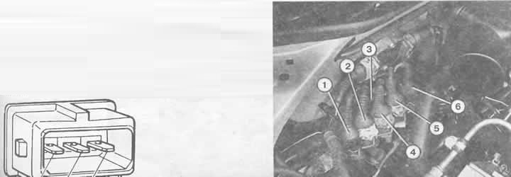
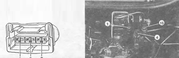
Right: Plug connections at the rear right of the engine compartment on a model with a 6-cylinder engine:
1 - for heating the right lambda probe;
2 - for ignition coil (supply wiring);
3 — for the lambda probe signal (right lambda probe; the plug connection is located at the back behind the fastener);
4 - for knock sensor I;
5 — for the engine shaft speed sensor;
6 — for the ignition timing sensor.
Below: The figure shows the location of the contacts of the engine speed and ignition timing sensor plug.
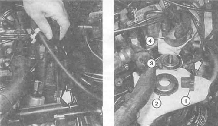
Open the ignition distributor: use a screwdriver to press the fastening brackets (arrows), lift the distributor cover (4) from the housing (3), remove the distributor runner (1), remove the dust cover (2).
Checking the ignition timing sensor. For a 6-cylinder engine
The ignition timing sensor is installed on the left rear directly in the cylinder block. It should be checked through the gray three-pin plug connection on the rear wall of the engine compartment. The check itself is similar to the check of the engine speed sensor, which is described in the previous section.
Checking the control unit
For control unit (electronic ignition system or ignition and injection system) there is no test method in the usual sense of the word. However, you can find the cause of the malfunction by interrogating the fault memory (chapter "Regular Maintenance"). The control unit of the electronic ignition system is located under the trim of the front passenger's footwell (chapter "Body electrical system").
(Material republished from the website «AUDImanual.ru»)