
Table of contents: Removal the ignition switch ↓ Short circuit of ignition ↓
In this book we want to address only the electrical part of the ignition switch. Repair of the lock mechanism should be carried out by a workshop, because to remove it, it is necessary to drill the housing in a certain place.
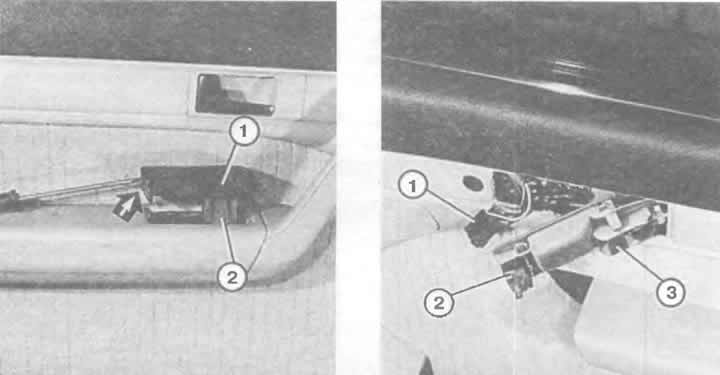
Left: Using a narrow screwdriver, remove the retaining clip from the groove along the rear edge of the switch block (arrow). Individual switches (2) can be removed from the switch block by inserting a thin screwdriver along the switch body.
Right: Removing the window switch on the right door is done after removing the door handle (chapter "Body parts") and removing the door opening handle (3). The window lift switch (2) can be removed after carefully disconnecting the plug.
With the instrument cluster and upper steering column trim removed, one of the two headless screws (2) holding the ignition switch (3) with the connected plug (1) on the switch element is visible.
Removal the ignition switch
Remove the instrument panel (see beginning of chapter). The steering wheel lock is now accessible from above.
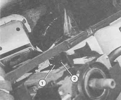
Remove the protective varnish and unscrew the two small screws on the right and left of the fastening element with the steering wheel lock switches.
Remove (back) the switch.
When installing a new switch, make sure that the drive pin of the lock enters the recess on the switch.
Screw in the screws and apply a protective varnish.
Short circuit of ignition
The ignition key must be able to turn in the ignition switch to release the steering lock. If the steering lock is faulty, you cannot continue driving, otherwise the steering wheel may lock while driving.
Remove the shelf on the left under the instrument panel (chapter "Salon").
Disconnect the multi-pin plug at the ignition switch. The wire tips that will be used to short-circuit are now free.
Now connect, for example with a paper clip, the contacts of the red and black wires so that the ignition turns on
To start the engine using the starter, build an insulated second wire bridge that will first connect to the red and black wire.
The second wire bridge is quickly connected to the other bridge and immediately disconnected again: the starter starts the engine.
Remove the second bridge and insulate the first one well so that they do not touch each other with exposed areas again. Otherwise, a short circuit will occur, since the red wire does not have a fuse.
To stop the engine, you need to disconnect the red and black wires.
(A link to the original source is available on the website «AudiManual»)