
Repair Chevrolet Repair Toyota Repair Honda Repair AvtoVAZ Repair Mercedes-Benz Repair BMW Repair Opel
Home  |  Contacts  |  Sitemap  |    
English Русский
Български
Беларускі
Український
Српски
Hrvatski
Română
Polski
Slovenský
Magyar
AudiManual.ru


  • AUDI 80
  • AUDI 100
  • AUDI A3
  • AUDI A4
  • AUDI A6
  • AUDI A8
  • AUDI Q
  • OTHER
  • ARTICLES
C4 (1990-1994) C4 (1990-1994, petrol) C3 (1982-1990) C3 (1982-1990, petrol) C3 (1982-1990, diesel)

Instrument cluster elements (Audi 100 C4)

  • Home
  • Audi 100
  • C4 (1990-1994, petrol)
  • Electrical equipment
  • Equipment and devices
  • Instrument cluster elements
            0

Disassembly


In our description we adhere to the most frequently installed VDO instrument cluster on the Audi-100:

Without disassembling the instrument cluster panel, you can remove the following elements from the back side:

Ambient temperature indicator: Remove the two Phillips head screws on the indicator block, then two more at the plug.

Light/radio buzzer: remove the mounting bracket from the instrument panel.

Indicators (control lamps): If you need to get to all the indicators, you need to remove the 2 TORX screws on top of the instrument cluster. Then you can fold the back cover of the housing down. The indicator bulbs in Audi are firmly soldered into their sockets and can only be purchased as a single unit. When buying a spare bulb, pay attention to the color of the socket: 1.1-watt, 1.2-watt and 2-watt bulbs are installed (with differently colored cartridges). To remove it, turn the cartridge a quarter turn to the left and pull it out.

Scale illumination: see "Indicators".

Adjustment resistor for scale illumination: loosen 2 TORX screws and fold back the housing cover down. Unscrew two hex nuts, remove the adjustment resistor.

Plug with code for on-board computer: remove.

Control unit for mini-test (auto-self-checks) on-board computer: loosen 2 TORX screws and fold back the instrument cluster housing cover downwards. Unscrew the control unit from the inside of the instrument cluster housing cover.

After disassembling the instrument cluster (to do this, remove the 8 screws from the outside on the back of the device, lift the main plate) the following elements become available.


Speedometer: carefully remove from plug connections and remove.

Watch with a regular dial (large size in the instrument panel): carefully remove from plug connections.

Tachometer: Unscrew the three screws on the back of the device.

Digital Clock: Remove the tachometer. Remove the two small slotted screws on the digital clock and pull the clock forward.

Fuel quantity indicator or temperature indicator: unscrew two hex nuts on the back side. Remove the front part of the housing from the fastening hooks.

Self-check system (mini) (coolant/Brake/Oil Pressure Indicator Block): remove the tachometer or large digital clock, loosen the two slotted screws, remove the indicator block from the connecting contacts.

Self-test system (auto): like a mini-test.

Instrument cluster printed circuit board: remove all control devices, as well as the adjustment resistor for the scale illumination. Loosen the screw connections, remove the board.

Voltage stabilizer: soldered to the printed circuit board.
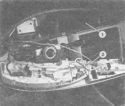
The combined instrument panel (2) is removed from its mounting location (1) with the wires still…

The combined instrument panel (2) is removed from its mounting location (1) with the wires still connected.
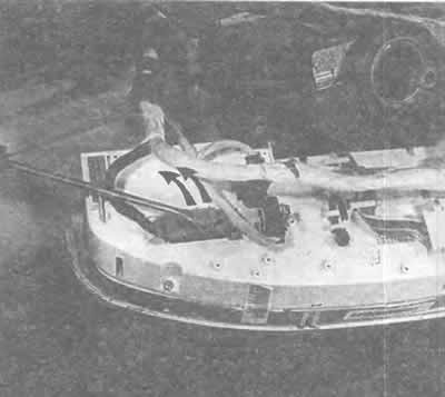

This plug on the combined instrument cluster can only be removed after lifting up (arrows) this…

This plug on the combined instrument cluster can only be removed after lifting up (arrows) this plastic bracket. On the plug next to it, you need to squeeze two plastic brackets.
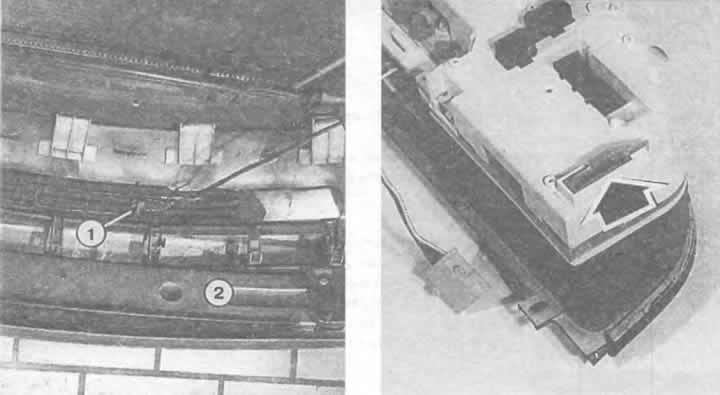

Left: With the bumper (2) removed, the ambient temperature sensor (1) is visible, which provides…

Left: With the bumper (2) removed, the ambient temperature sensor (1) is visible, which provides information to the instrument panel.

Right: On the left edge of the combined instrument panel is the so-called code plug (arrow), which in cars with an on-board computer has different designations accepted in different countries.


Material republished from the website audimanual.ru
The article was checked by auto expert Nikita Rudakov
This article is available at russian, bulgarian, belarusian, ukrainian, serbian, croatian, romanian, polish, slovak, hungarian

Share information:
Previous articles
Audi 100 C4: Equipment and devices
Next articles

Checking indicators and alarms
Speedometer
Tachometer
Watch
Fuel quantity indicator


Similar articles on other Audi car models:
Removal and installation the instrument cluster Audi 80 B2 (1979-1986)
Instrument cluster unit, combi-processor in instrument cluster… Audi A3 Type 8L (1996-2003)
Instrument cluster lights Audi A4 B5 (1994-2001, petrol)
Instrument cluster Audi A6 C5 (1997-2004)
Instrument cluster Audi A8 D2 (1994-2002)
Instrument cluster and indicator lamp assignment table Audi Q7 Typ 4L (2005-2015, diesel)
Instrument cluster — select language Audi A2 (1999-2005)
Link to this page in different formats


Visitor comments

No comments yet


How much will 32 + 44 =


100(C4, 1990-1994) 
  • General information
  • User manual
  • Power unit
  • Engine repair
  • Ignition system
  • Fuel system (gasoline)
  • Fuel system (diesel)
  • Lubrication system
  • Cooling system
  • Exhaust system
  • Transmission
  • Clutch
  • Car gearbox
  • Drive shafts
  • Chassis
  • Car suspension
  • Steering
  • Wheels and tires
  • Brake system
  • Body
  • Ventilation and heating
  • Body repair
  • Electrical equipment
  • Power devices
  • Lighting and appliances
  • Electrical circuits
 
100(C4, 1990-1994, petrol) 
  • General information
  • Operation and maintenance
  • Power unit
  • Engine repair
  • Exhaust system
  • Cooling system
  • Supply system
  • Air filter
  • Mono-Motronic injection system
  • Digifant injection system
  • KE-III-Jetronic and KE-Motronic
  • MPI and MPFI injection system
  • Transmission
  • Clutch
  • Car gearbox
  • Chassis
  • Suspension and steering
  • Brake system
  • Wheels and tires
  • Body
  • Exterior
  • Interior
  • Electrical equipment
  • Fuses and relays
  • Power devices
  • Ignition system
  • Lighting and signaling
  • Equipment and devices
  • Electrical circuits
 
100(C3, 1982-1990) 
  • General information
  • User manual
  • Maintenance
  • Specifications
  • Power unit
  • Engines 4-cylinder
  • Engines 5-cylinder
  • Diesel engine
  • Cooling system
  • Power system (carburetor)
  • Power system (injector)
  • Fuel system (diesel)
  • Transistor ignition system
  • Electronic ignition system
  • Transmission
  • Clutch
  • 4 speed gearbox 014
  • 5 speed gearbox 013 and 093
  • 5 speed gearbox 016 and 012
  • Shift mechanism KP 016
  • Automatic transmission
  • Front wheel drive
  • Chassis
  • Front suspension
  • Rear suspension
  • Steering
  • Brake system
  • Body
  • Body elements
  • Electrical equipment
  • Lighting and appliances
  • Power devices
  • Electrical circuits
 
100(C3, 1982-1990, petrol) 
  • General information
  • Maintenance and operation
  • 4 cylinder engine
  • Engine repair
  • Cooling and lubrication system
  • Supply system
  • Ignition system
  • 5 cylinder engine
  • Engine repair
  • Cooling and lubrication system
  • Supply system
  • Ignition system
  • Transmission
  • Clutch and drive shafts
  • 4 speed gearbox 014
  • 5 speed gearbox 013 and 093
  • 5 speed gearbox 016 and 012
  • Automatic gearbox
  • Chassis
  • Steering
  • Front suspension
  • Rear suspension
  • Brake system
  • Body
  • Body elements
  • Doors, locks and windows
  • Body repair
  • Electrical equipment
  • Equipment and devices
  • Power devices
  • Electrical circuits
 
100(C3, 1982-1990, diesel) 
  • General information
  • User manual
  • Maintenance
  • Troubleshooting
  • Power unit
  • Engine in a car
  • Engine removed
  • Cooling system
  • Fuel system
  • Exhaust system
  • Starting and charging
  • Preheating
  • Transmission
  • Clutch
  • Mechanical gearbox
  • Automatic gearbox
  • Drive shafts
  • Chassis
  • Brake system
  • Suspension
  • Steering
  • Body
  • Exterior
  • Interior
  • Electrical equipment
  • Equipment and devices
  • Electrical circuits
 
AudiManual.ru © 2017-2026 · Mobile version · Feedback · Sitemap: EN BG BY UA RS HR RO PL SK HU · Site search · News and articles
80 B2 · 80 B3 petrol · 80 B3 · 80 B4 · 100 C3 diesel · 100 C3 petrol · 100 C3 · 100 C4 petrol · 100 C4 · A3 Type 8L · A4 B5 petrol · A4 B5 · A4 B6 petrol · A4 B6 · A4 B7 · A4 B8 · A6 C4 · A6 C5 · A6 C5 Allroad · A8 D2 · Q5 Type 8R · Q7 Typ 4L · Audi A2 ·
This site uses cookies 🍪. Click the button to accept this fact.