Repair Chevrolet Repair Toyota Repair Honda Repair AvtoVAZ Repair Mercedes-Benz Repair BMW Repair Opel
Home  |  Contacts  |  Sitemap  |    
English Русский
Български
Беларускі
Український
Српски
Hrvatski
Română
Polski
Slovenský
Magyar
AudiManual.ru


  • AUDI 80
  • AUDI 100
  • AUDI A3
  • AUDI A4
  • AUDI A6
  • AUDI A8
  • AUDI Q
  • OTHER
  • ARTICLES
B8 (2007-2015) B7 (2004-2008) B6 (2000-2006) B6 (2000-2006, petrol) B5 (1994-2001) B5 (1994-2001, petrol)

Instrument cluster lights (Audi A4 B5)

  • Home
  • Audi A4
  • B5 (1994-2001, petrol)
  • Electrical equipment
  • Lighting and lamps
  • Instrument cluster lights
            0
Table of contents: Instrument lighting ↓ Heating lever illumination ↓ Lighting of the manual control unit… ↓ Front ashtray/cigarette lighter… ↓ Glove Box Light ↓ Gear indicator ↓ Light bulbs in switches ↓

Instrument lighting


This section deals with the illumination of the indicator instruments. A description of the indicator lights, also located in the combined instrument panel, can be found in Chapter Tools and instruments. Dismantling the instrument lighting:

1. Remove the steering wheel (chapter Wheel suspension and steering).

2. Remove the combination instrument (chapter Tools and instruments).

3. Depending on the model, up to nine bulb sockets for instrument lighting are visible behind the combination instrument.

4. To replace, turn them to the left and remove them.

5. Glass-base bulbs of 1.1 W each form a single structural element with the socket.

6. Reinsert the lamp holder into the combination instrument and turn it to the right until it stops.

7. In vehicles with an on-board computer, five 1.1 W glass-base bulbs are used to illuminate the display.

8. Some instrument light bulbs, depending on the manufacturer, are equipped with orange protective caps. The caps can be installed on new incandescent bulbs.

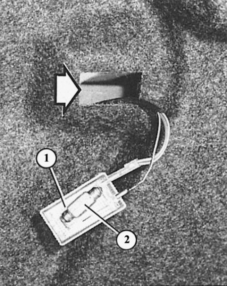
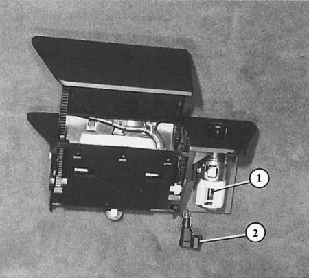
The side light of the trunk is identical to the upper light of the trunk. The arrow shows the mounting hole for the lamp housing (1); the number "2" indicates an incandescent lamp.

The side light of the trunk is identical to the upper light of the trunk. The arrow shows the…


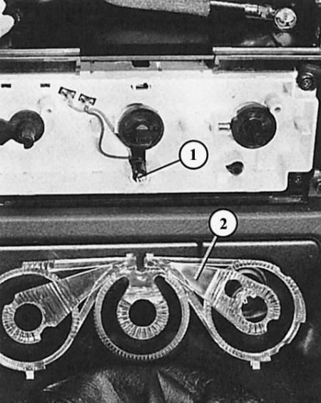
A small light bulb (1) is used to illuminate the heating regulator. Through one light guide (2; here removed from the clamps) the lighting is distributed across all three scales of the adjustment knobs.


A small light bulb (1) is used to illuminate the heating regulator. Through one light guide (2;…


A small light bulb (1) is used to illuminate the heating regulator. Through one light guide (2;…


Four small bulbs are used to illuminate the manual climate control unit. The socket and bulb form one structural element that can be replaced with a screwdriver (turn a quarter turn to the left).

Four small bulbs are used to illuminate the manual climate control unit. The socket and bulb form…


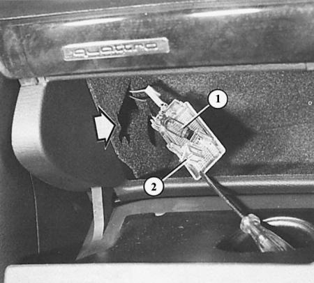
Glove box light: carefully pry the bulb housing (2) out of the mounting hole using a screwdriver. The spotlight bulb (1) is now accessible.


Glove box light: carefully pry the bulb housing (2) out of the mounting hole using a screwdriver.…


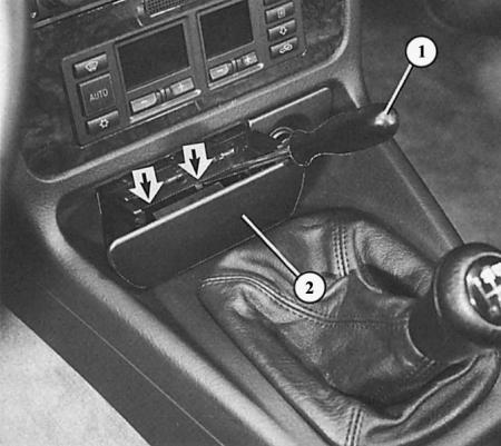
Removing the ashtray/cigarette lighter housing: open the ashtray (2), use a screwdriver (1) to remove the springs from the grooves in both recesses (arrows) and pull the housing back.

Removing the ashtray/cigarette lighter housing: open the ashtray (2), use a screwdriver (1) to…


Here the ashtray/cigarette lighter light bulb (2) has been removed from the cigarette lighter (1) with the ashtray housing removed and turned over.

Heating lever illumination


1. Remove the radio receiver (chapter Tools and instruments).

2. Loosen the four screws in the radio mounting hole.

3. Remove the center console trim panel (the switches remain in place).

4. Pull back all three heating/ventilation rotary controls.

5. Unscrew the two Phillips-head screws underneath and remove the trim panel.

6. Remove the light guide from the clamps.


7. Now you can see the 1.2W glass-base bulbs inserted here.

8. The bulbs can be removed from the socket one by one.

Lighting of the manual control unit of the air conditioning system


1. Remove the radio receiver from the clamps (chapter Tools and instruments).

2. Loosen the four screws in the radio mounting hole.

3. Remove the center console trim panel (the switches remain in place).

4. Unscrew the four mounting screws of the manual climate control unit and remove the unit.

5. On the back side, turn the lamp holders to the left and remove them.

6. Bulbs with glass bases of 2 W each form a single structural element with the socket.

7. Both middle bulbs have a black border, both outer ones do not.

Front ashtray/cigarette lighter lighting


1. Open the ashtray (2) in the center console.

2. Insert a screwdriver into one of the two recesses behind the ashtray and press down on the retaining spring at the base of the ashtray housing.

3. This is easier to do if you shine a hand torch into the recess.

4. Repeat the same process with the second spring.

5. Remove the ashtray back together with the body.

6. Lift the small mounting plate and remove the bulb socket on the cigarette lighter.

7. Replace the lamp.

Glove Box Light


The glove box light is energized when the parking or side lights are on. It is switched on and off by a contact switch in the hinge.

1. Open the glove box.

2. Insert a screwdriver into the recess on the side of the lamp housing and carefully pry the lamp out.

3. After replacing the incandescent lamp (spotlight bulb 5W, length 36mm) reinsert the lamp housing, first with the side with the wire.


Gear indicator


A glass-base lamp is used to illuminate the gear indicator on the automatic transmission selector lever (1.2 W, form W according to DIN standard).

1. Remove the center console (chapter Salon).

2. Remove the bulb holder from the clamps on the left side of the selector lever console.

3. Remove the glass base lamp from the socket.

Light bulbs in switches


Almost all switches have illuminated symbols, but this lighting is not intended to be replaced. Therefore, in case of a defect, the unlit switch must be taken into account or replaced.

This article was copied from the website AudiManual.ru
The article was checked by auto expert Georgy Rodionov
This article is available at russian, bulgarian, belarusian, ukrainian, serbian, croatian, romanian, polish, slovak, hungarian

Share information:
Previous articles
Audi A4 B5: Lighting and lamps
Next articles

Interior light
License plate lights
Rear lights
Front direction indicator lights
Checking the direction indicator and hazard warning system
Checking the brake lights
Help with brake light malfunctions
Checking the horn


Similar articles on other Audi car models:
Removal and installation the instrument cluster Audi 80 B2 (1979-1986)
Instrument panel and indicator lights Audi 100 C3 (1982-1990, diesel)
Instrument cluster unit, combi-processor in instrument cluster… Audi A3 Type 8L (1996-2003)
Diagram 4-17. Instrument cluster, indicator lights Audi A6 C5 Allroad (1999-2005)
Instrument cluster Audi A8 D2 (1994-2002)
Instrument cluster and indicator lamp assignment table Audi Q7 Typ 4L (2005-2015, diesel)
Instrument cluster — select language Audi A2 (1999-2005)
Link to this page in different formats


Visitor comments

No comments yet


How much will 15 + 43 =


A4(B8, 2007-2015) 
  • General information
  • Operating instructions
  • Power unit
  • Petrol engines 1.8 l
  • Petrol engines 1.8/2.0 l
  • Petrol engines 3.0 l
  • Petrol engines 3.2 l
  • Fuel system (petrol)
  • Diesel engines 2.0 l (CA*)
  • Diesel engines 2.0 l (CJCB)
  • Diesel engines 2.7/3.0 l
  • Diesel engines 3.0 l
  • Fuel system (diesel)
  • Transmission
  • Manual gearbox 0B1
  • Manual gearbox 0B2
  • Manual gearbox 0B3
  • Manual gearbox 0B4
  • Automatic transmission 0B5
  • Automatic transmission 0B6
  • Automatic transmission 0AW
  • All-wheel drive system
  • Chassis
  • Front suspension
  • Rear suspension
  • Brake system
  • Steering system
  • Body
  • Exterior
  • Interior
  • Seats
  • Doors, locks and windows
  • Security system
  • Heating and air conditioning
  • Electrical equipment
  • Audio system
  • Power devices
  • Equipment and devices
  • Lighting and lamps
  • Electrical circuits
 
A4(B7, 2004-2008) 
  • General information
  • Introduction to manual
  • Troubleshooting
  • Operating instructions
  • Maintenance
  • Power unit
  • Petrol engines 2.0 (ALT)
  • Petrol engines 2.0 (TFSI)
  • Petrol engines 1.8 (MPI)
  • Diesel engines
  • Cooling system
  • Air conditioner
  • Fuel and exhaust system
  • Ignition system
  • Starting and charging
  • Transmission
  • Clutch
  • Manual gearbox
  • Automatic gearbox
  • Drive shafts
  • Chassis
  • Brake system
  • Front suspension
  • Rear suspension
  • Steering
  • Body
  • Exterior
  • Interior
  • Electrical equipment
  • Equipment and devices
  • Lighting and signaling
  • Windscreen wipers and washers
  • Electrical diagrams
  • Electrical diagrams (since 2007)
 
A4(B6, 2000-2006) 
  • General information
  • Vehicle Description
  • User manual
  • Maintenance
  • Power unit
  • Gasoline engine
  • Diesel engine
  • Lubrication system
  • Cooling system
  • Supply system
  • Injection system
  • Exhaust system
  • Ignition and control
  • Transmission
  • Gear box
  • Clutch and drive shafts
  • Chassis
  • Brake system
  • Car suspension
  • Steering
  • Body
  • Heating and ventilation
  • Exterior (external elements)
  • Interior (internal elements)
  • Electrical equipment
  • Power devices
  • Lighting and appliances
  • Electrical circuits
 
A4(B6, 2000-2006, petrol) 
  • General information
  • Introduction to the guide
  • Car care
  • Power unit
  • Engine repair
  • Lubrication system
  • Cooling system
  • Injection and control system
  • Ignition system
  • Power and exhaust system
  • Transmission
  • Clutch and drive shafts
  • Car gearbox
  • Chassis
  • Suspension and wheels
  • Steering
  • Brake system
  • Body
  • Interior
  • Exterior
  • Electrical equipment
  • Equipment and devices
  • Lighting and signaling
  • Power devices
  • Electrical circuits
 
A4(B5, 1994-2001) 
  • General information
  • Introduction to the guide
  • Car care
  • Maintenance (gasoline)
  • Maintenance (diesel)
  • Power unit
  • Gasoline engines
  • Diesel engines
  • Engine overhaul
  • Cooling system
  • Fuel injection (gasoline)
  • Fuel system (diesel)
  • Exhaust system
  • Ignition system
  • Transmission
  • Clutch
  • Mechanical gearbox
  • Automatic gearbox
  • Drive shafts
  • Chassis
  • Brake system
  • Car suspension
  • Steering
  • Body
  • Exterior
  • Interior
  • Doors, locks and windows
  • Heating and ventilation
  • Electrical equipment
  • Power devices
  • Equipment and devices
  • Electrical circuits
 
A4(B5, 1994-2001, petrol) 
  • General information
  • Vehicle description
  • Maintenance
  • Power unit
  • Engine repair
  • Turbocharging
  • Exhaust system
  • Cooling system
  • Ignition system
  • Fuel system
  • Motronic injection system
  • MPI and MPFI injection system
  • Transmission
  • Clutch
  • Gearbox and shafts
  • Chassis
  • Steering
  • Car suspension
  • Brake system
  • Wheels and tires
  • Body
  • Heating and ventilation
  • Body parts
  • Electrical equipment
  • Fuses and relays
  • Power devices
  • Lighting and lamps
  • Tools and devices
  • Electrical circuits
 
AudiManual.ru © 2017-2026 · Mobile version · Feedback · Sitemap: EN BG BY UA RS HR RO PL SK HU · Site search · News and articles
80 B2 · 80 B3 petrol · 80 B3 · 80 B4 · 100 C3 diesel · 100 C3 petrol · 100 C3 · 100 C4 petrol · 100 C4 · A3 Type 8L · A4 B5 petrol · A4 B5 · A4 B6 petrol · A4 B6 · A4 B7 · A4 B8 · A6 C4 · A6 C5 · A6 C5 Allroad · A8 D2 · Q5 Type 8R · Q7 Typ 4L · Audi A2 ·
This site uses cookies 🍪. Click the button to accept this fact.