
Table of contents: Dismantling the combination… ↓ Replacing the indicator lights in… ↓ Faulty combination instrument ↓ Disassembling the combination… ↓
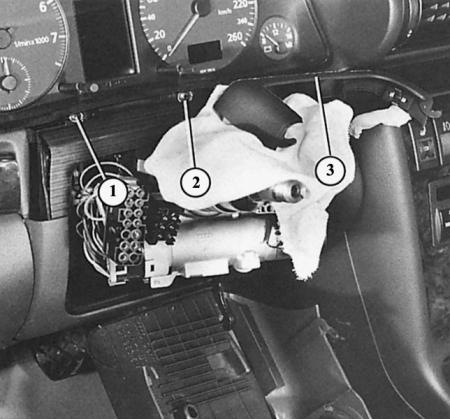
Here we have removed the combination instrument cluster trim panel (3) to expose both Phillips-head mounting screws (1 and 2).
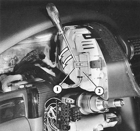
The multi-pin connector (2) can be removed from the combination instrument by pressing the plastic clip (1) high.
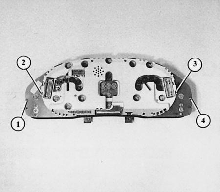
To remove the rear cover of the combination instrument, you must first loosen both TORX screws 2 and 3. The numbers 1 and 4 indicate two of the four screws that must be loosened in order to unscrew the board.
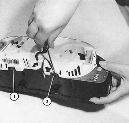
Removing the rear cover of the combination instrument: after loosening the screws, there are only six plastic clips to open (two of them are shown as "1" and "2").
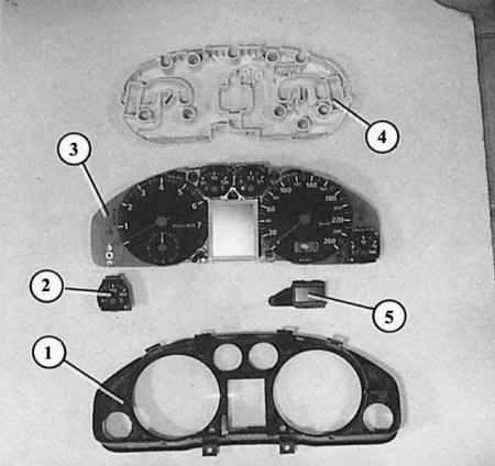
Disassembled combination instrument: 1 – decorative panel; 2 – oil temperature indicator; 3 – board with devices; 4 – back cover; 5 – liquid crystal display.
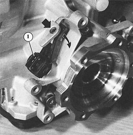
On the left front of the gearbox you can see the tachometer pulse sensor (1). To remove the pulse sensor, press the locking tab down (straight arrow), turn the pulse sensor (curved arrow) and remove it from the gearbox. When installing, lubricate the rubber O-rings with Vaseline.
Dismantling the combination instrument
1. Open the steering wheel adjustment device, pull the steering wheel back and press down.
2. Remove the steering wheel (chapter Wheel suspension and steering).
3. Remove the upper cover of the lever switches behind the steering wheel. To do this, loosen the two Phillips-head screws at the bottom of the trim on the right and left and remove the upper part of the trim.
4. Fold back the decorative panel under the combination instrument.
5. Loosen the two Phillips head screws at the bottom of the combination meter.
6. Carefully remove the combination instrument from the instrument panel.
7. Loosen the clamp (push the plastic clamp up high or release the latches), carefully remove the multi-pin connector.
Tip: When replacing the combined instrument, the workshop must transfer the mileage information from the old instrument to the new one. For this purpose, the VAG 1551 computer reader is used. In the same way, if necessary, the fuel level indicator, fuel consumption indicator and service interval indicator are adjusted.
Replacing the indicator lights in the combination instrument
The indicator lights are changed from the back of the combined instrument without further disassembly. The indicator light bulbs in Audi are firmly soldered to their sockets and are sold as spare parts only as a set. When buying them, take into account the color of the sockets: 1.1 W and 1.2 W bulbs are installed with sockets of different colors. To remove the bulb socket, turn it a quarter turn to the left and remove it.
The same applies to the scale lighting. But note that some of these bulbs have orange caps. The caps are replaced with new bulbs.
Faulty combination instrument
Unfortunately, Audi only offers the combination instrument as a complete replacement. Individual components are not sold, so if it malfunctions, you'll have to dig deep into your pocket.
Anyone who is not afraid of electronics can, at a minimum, dare to disassemble the combination device and inspect the board for obvious defects.
Disassembling the combination instrument
1. Remove the rear cover of the combination instrument. To do this, loosen the two TORX screws on the left and right and press back the six plastic clips.
2. Unscrew the board (four more TORX screws).
3. The speedometer and tachometer are soldered with connectors; a smaller instrument is connected to a larger one to form a single structural element.
4. Additional tools for measuring oil temperature and on-board voltage are removed separately (hexagonal nut on the back side; inserted connectors).