
Table of contents: Removal the control module ↓ Troubleshooting the self-diagnostic… ↓ Independent control of the indicator… ↓ Additional functions on the… ↓
As a special feature, the Audi 100 offers a self-diagnosis system. It monitors eight functions or operating states after the ignition is switched on and after the low beam or brake light is switched on. Active monitoring is also carried out while driving. The self-diagnosis system thus replaces a number of the conventional indicators present in the standard version.
The fault indicators, the display of which is located in the middle of the instrument cluster, are divided into the groups "Danger signal" and "Warning signal".
Malfunctions that significantly affect traffic safety or result in serious damage are considered dangerous and therefore the signals light up red. These are the following signals:
Brake system: brake fluid level too low.
Engine oil pressure: oil pressure at idle drops below 0.3 bar, or at speeds exceeding 2100 rpm, 1.8 bar is not reached (models with 4- and 5-cylinder engines and with 6-cylinder engines from 7/91) or 2.5 bar (models with 6-cylinder engines from 8/91).
Coolant: The coolant temperature rises above 120°C, or the operating temperature is not reached, or the coolant level is too low. In addition to the visual hazard signal, the buzzer sounds three times from the instrument cluster. Hazard signals have priority over warning signals in the system. As long as a hazard signal exists, the warning signal is suppressed. It only appears after the cause of the hazard signal has been eliminated.
Warning signals are displayed on the panel in yellow and are accompanied by a single buzzer. These are the following signals:
Brake light: This symbol appears immediately after the ignition is switched on. If you press the brake pedal, the symbol disappears - provided that both brake lights are functioning.
Lighting: The self-test system cannot perform this test step completely automatically. First, the driver must switch on the low beam. The low beam and the rear lights are checked at the same time. The system is not able to indicate a simultaneous failure of both filaments of the low beam or the rear lights. But in general, this malfunction is unlikely to occur.
Battery: The battery symbol flashes when the battery voltage is outside the standard range of 10.6-15.6 V.
Windscreen washer system: This indicator indicates that the washer fluid level in the reservoir is too low.
Fuel tank: The fuel symbol lights up when there are only 12 litres of petrol left in the fuel tank. If there are several faults on the warning light panel, the warning lights flash in turn when the ignition is switched on.
The "OK" signal should appear if the inscription goes out after turning on the ignition and pressing the brake pedal "Bremslicht" (stop signal). "OK" in this case means that all stages of the test were passed without any fault messages. After a short time, the signal goes out.
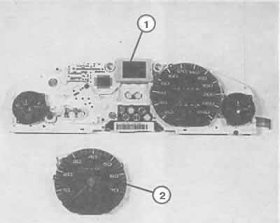
After removing the tachometer (2), the printed circuit board and the indicator board of the self-checking and self-diagnostic system (1) are unscrewed from the main one.
The control station for car lighting functions in a completely different way. These devices work on the electromagnetic principle and compare the current flowing in the wiring, for example, to the left and right low beam. If there is no current flow in any wire due to a break or defective lamp, the control device determines the difference and informs the control unit about it. In the event of a malfunction of both lamps, which happens very rarely, naturally, no difference is noted either. In this case, the control device is not able to determine the malfunction.
Hint: When connecting the trailer connector, make sure that the wires are connected to the rear side lights before the lamp tester (it is located at the rear left in the luggage compartment). If power is taken from one of the rear side lights, then when the trailer lighting is connected, the lamp health detection device receives unaccounted information about the currents in the circuit, and it reports a "lamp defect".
Removal the control module
The control unit of the automatic check system is screwed on the back of the instrument cluster in the same housing as the indicator unit. A description of how to remove the automatic check system module can be found at the beginning of this chapter in the section "Disassembly".
Troubleshooting the self-diagnostic system
Control of the self-diagnostic system at home is only partially possible: first, you should check all the sensors - if the fault was not found here, then it should be looked for in the self-diagnostic system module.
The sensors are checked in the same way as when checking the indicators of a regular instrument panel, see previous pages.
The water level sensor in the cooling system, which is installed only in the autotest system, is checked as follows: if the indicator lights up despite the cooling system tanks being full, disconnect the cable plugs at the tank. If the warning signal now goes out, the sensor is faulty.
Checking devices to determine faults in front and rear lamps (installation location: relay box on the left rear in the engine compartment) you must provide the workshop.
Independent control of the indicator block
Press with the ignition on and stationary (or moving at a maximum speed of 5 km/h) car button on the lower left side of the instrument cluster.
If the indicators and the system are working properly, all the signal symbols should appear on the instrument panel one by one.
Such a check is not possible if the danger signal is on.
Additional functions on the self-diagnostic system display
Speed warning: after recording the current speed, the autodiagnostic system indicates that this speed has been significantly exceeded by displaying a symbol and a buzzer. This recording is retained until the ignition is switched off, unless another speed has been recorded or the memory has been erased (hold the leftmost button down for a second).
Radio frequency indicator: if the indicator field is not occupied by information from the self-test system, then the frequency data of radio stations on the correspondingly equipped car radios appears on it. If the radio stations also transmit signals of the radio data system, then the inscription "RDS" appears in the indicator field. Then the name of the radio station can be read on the radio display.
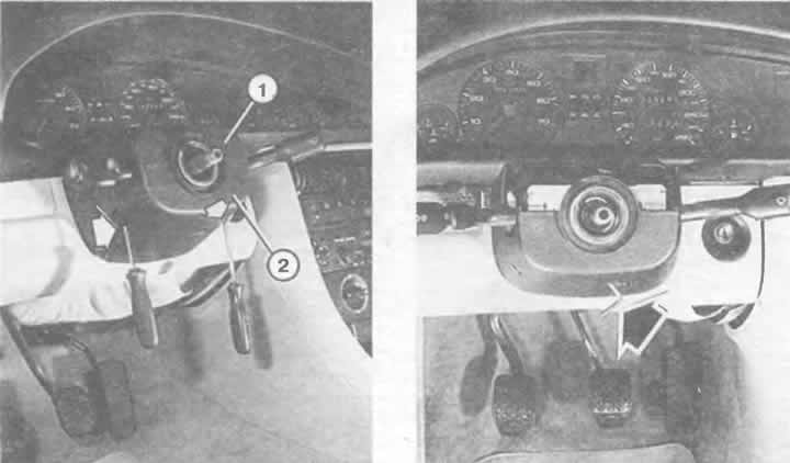
Removing switches.
Left: Loosen the two Phillips head screws (arrows) with the relay removed. Disconnect the upper trim (1) from the lower trim (2).
Right: The lever on the column is loosened by unscrewing the diagonally located clamping screw using an Allen key (arrow) or a Phillips-head screwdriver on earlier model vehicles.
(Content source: the specified website «AUDImanual.ru»)