Repair Chevrolet Repair Toyota Repair Honda Repair AvtoVAZ Repair Mercedes-Benz Repair BMW Repair Opel
Home  |  Contacts  |  Sitemap  |    
English Русский
Български
Беларускі
Український
Српски
Hrvatski
Română
Polski
Slovenský
Magyar
AudiManual.ru


  • AUDI 80
  • AUDI 100
  • AUDI A3
  • AUDI A4
  • AUDI A6
  • AUDI A8
  • AUDI Q
  • OTHER
  • ARTICLES
C4 (1990-1994) C4 (1990-1994, petrol) C3 (1982-1990) C3 (1982-1990, petrol) C3 (1982-1990, diesel)

High voltage elements (Audi 100 C4)

  • Home
  • Audi 100
  • C4 (1990-1994, petrol)
  • Electrical equipment
  • Ignition system
  • High voltage elements
            0
Table of contents: High voltage wires ↓ Spark plug tips, tips with… ↓ Firing order ↓

High voltage wires


The high-voltage part of the ignition system includes, in addition to the ignition coil and distributor - which have already been discussed - also high-voltage wires, wire tips with an interference-suppressing resistor and, of course, spark plugs.

Thick connecting wires running from the ignition coil to the distributor or from the distributor to the spark plugs (models with 6-cylinder engine without distributor), usually do not cause any trouble. They should be firmly inserted with their tips and noise suppression resistors (radio interference elimination) into the sockets of the ignition distributor cap. Their plug connections must not be oxidized and they must have good contact with the tips of the spark plugs.

TDC — position of the ignition distributor: the contact plate of the distributor rotor should be…

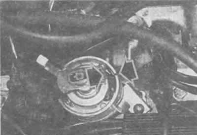
TDC — position of the ignition distributor: the contact plate of the distributor rotor should be opposite the mark on the edge of the housing (arrow). The mark is visible when the dust cover is removed.


If the high-voltage wires have become stiff and brittle, new ones should be installed. For a 6-cylinder engine, they can be purchased complete with both plugs.


For 4 and 5 cylinder engines, you will need to purchase the required length of high-tension wire and the associated brass terminals for the ends of the cable from a parts store. Press the brass terminals onto the ends of the cable, slide the spark plug caps and the terminals with interference suppression resistors on until they lock into place.

Hint: "leaky" spots in high-voltage wires can be easily spotted if you look into the engine compartment at night with the engine running. Then the ignition sparks jumping on the cable are clearly visible.


Spark plug tips, tips with interference suppression resistors


Only certain spark plug caps can be used in Audi. Suitable caps must have a self-resistance of 4-6 kOhm.

The same applies to the tips with interference suppression resistors installed on the distributor and ignition coil connections. Their own resistance should be 0.6-1.4 kOhm.

The distributor rotor must also have a specific 0.6-1.4 kOhm interference suppression resistor. It is marked "R1".

Hint: If the engine constantly or occasionally (in wet weather) does not work on all cylinders, this can often be due to faulty spark plug tips. There is a spark leak through the insulating material between the metal shell and the high-voltage electrode. To check, replace the spark plug tip with another one. Roadside assistance: remove the metal shield of the plug.


Firing order


For smooth engine operation, the cylinders, for example, of a 4-cylinder engine, are not fired in the order 1-2-3-4, but in a certain sense of the word randomly. According to the firing order, high-voltage wires are connected to the distributor cap. If the distributor rotor, with the distributor cap and dust cover removed, points to the mark on the edge of the distributor housing, then cylinder 1 (first in the direction of movement) is at the ignition moment. This is the starting point when putting on the wires.


Firing order (cylinder firing order) in our engines is as follows:

4-cylinder engine: 1-3-4-2, distributor rotor rotates to the right (clockwise).

5-cylinder engine: 1-2-4-5-3, distributor rotor rotates to the right (clockwise).

6-cylinder engine: 1-4-3-6-2-5. No distributor - the order of the high-tension wire connections to the ignition coil pack corresponds to the order of the cylinders. Example: the high-tension wire from the rear right connection leads to the rear right cylinder.
The article was checked by auto expert Nikita Rudakov
This article is available at russian, bulgarian, belarusian, ukrainian, serbian, croatian, romanian, polish, slovak, hungarian

Share information:
Previous articles
Audi 100 C4: Ignition system
Next articles

Detonation combustion sensor
Ignition distributor
Ignition system diagnostics
Ignition system repair
Replacing spark plugs
Spark plugs
Checking the ignition timing


Similar articles on other Audi car models:
High voltage wires Audi 80 B4 (1991-1996)
Checking and adjusting the injection start of the high-pressure… Audi A3 Type 8L (1996-2003)
High voltage unit Audi A4 B5 (1994-2001, petrol)
Electrical diagram of high voltage circuit, ignition coil, spark… Audi A6 C5 (1997-2004)
Interior upholstery elements Audi A8 D2 (1994-2002)
High pressure pump Audi Q5 Type 8R (2008-2017)
Engine and gearbox mounting elements Audi A2 (1999-2005)
Link to this page in different formats


Visitor comments

No comments yet


How much will 19 + 20 =


100(C4, 1990-1994) 
  • General information
  • User manual
  • Power unit
  • Engine repair
  • Ignition system
  • Fuel system (gasoline)
  • Fuel system (diesel)
  • Lubrication system
  • Cooling system
  • Exhaust system
  • Transmission
  • Clutch
  • Car gearbox
  • Drive shafts
  • Chassis
  • Car suspension
  • Steering
  • Wheels and tires
  • Brake system
  • Body
  • Ventilation and heating
  • Body repair
  • Electrical equipment
  • Power devices
  • Lighting and appliances
  • Electrical circuits
 
100(C4, 1990-1994, petrol) 
  • General information
  • Operation and maintenance
  • Power unit
  • Engine repair
  • Exhaust system
  • Cooling system
  • Supply system
  • Air filter
  • Mono-Motronic injection system
  • Digifant injection system
  • KE-III-Jetronic and KE-Motronic
  • MPI and MPFI injection system
  • Transmission
  • Clutch
  • Car gearbox
  • Chassis
  • Suspension and steering
  • Brake system
  • Wheels and tires
  • Body
  • Exterior
  • Interior
  • Electrical equipment
  • Fuses and relays
  • Power devices
  • Ignition system
  • Lighting and signaling
  • Equipment and devices
  • Electrical circuits
 
100(C3, 1982-1990) 
  • General information
  • User manual
  • Maintenance
  • Specifications
  • Power unit
  • Engines 4-cylinder
  • Engines 5-cylinder
  • Diesel engine
  • Cooling system
  • Power system (carburetor)
  • Power system (injector)
  • Fuel system (diesel)
  • Transistor ignition system
  • Electronic ignition system
  • Transmission
  • Clutch
  • 4 speed gearbox 014
  • 5 speed gearbox 013 and 093
  • 5 speed gearbox 016 and 012
  • Shift mechanism KP 016
  • Automatic transmission
  • Front wheel drive
  • Chassis
  • Front suspension
  • Rear suspension
  • Steering
  • Brake system
  • Body
  • Body elements
  • Electrical equipment
  • Lighting and appliances
  • Power devices
  • Electrical circuits
 
100(C3, 1982-1990, petrol) 
  • General information
  • Maintenance and operation
  • 4 cylinder engine
  • Engine repair
  • Cooling and lubrication system
  • Supply system
  • Ignition system
  • 5 cylinder engine
  • Engine repair
  • Cooling and lubrication system
  • Supply system
  • Ignition system
  • Transmission
  • Clutch and drive shafts
  • 4 speed gearbox 014
  • 5 speed gearbox 013 and 093
  • 5 speed gearbox 016 and 012
  • Automatic gearbox
  • Chassis
  • Steering
  • Front suspension
  • Rear suspension
  • Brake system
  • Body
  • Body elements
  • Doors, locks and windows
  • Body repair
  • Electrical equipment
  • Equipment and devices
  • Power devices
  • Electrical circuits
 
100(C3, 1982-1990, diesel) 
  • General information
  • User manual
  • Maintenance
  • Troubleshooting
  • Power unit
  • Engine in a car
  • Engine removed
  • Cooling system
  • Fuel system
  • Exhaust system
  • Starting and charging
  • Preheating
  • Transmission
  • Clutch
  • Mechanical gearbox
  • Automatic gearbox
  • Drive shafts
  • Chassis
  • Brake system
  • Suspension
  • Steering
  • Body
  • Exterior
  • Interior
  • Electrical equipment
  • Equipment and devices
  • Electrical circuits
 
AudiManual.ru © 2017-2026 · Mobile version · Feedback · Sitemap: EN BG BY UA RS HR RO PL SK HU · Site search · News and articles
80 B2 · 80 B3 petrol · 80 B3 · 80 B4 · 100 C3 diesel · 100 C3 petrol · 100 C3 · 100 C4 petrol · 100 C4 · A3 Type 8L · A4 B5 petrol · A4 B5 · A4 B6 petrol · A4 B6 · A4 B7 · A4 B8 · A6 C4 · A6 C5 · A6 C5 Allroad · A8 D2 · Q5 Type 8R · Q7 Typ 4L · Audi A2 ·
This site uses cookies 🍪. Click the button to accept this fact.