
Repair Chevrolet Repair Toyota Repair Honda Repair AvtoVAZ Repair Mercedes-Benz Repair BMW Repair Opel
Home  |  Contacts  |  Sitemap  |    
English Русский
Български
Беларускі
Український
Српски
Hrvatski
Română
Polski
Slovenský
Magyar
AudiManual.ru


  • AUDI 80
  • AUDI 100
  • AUDI A3
  • AUDI A4
  • AUDI A6
  • AUDI A8
  • AUDI Q
  • OTHER
  • ARTICLES
B8 (2007-2015) B7 (2004-2008) B6 (2000-2006) B6 (2000-2006, petrol) B5 (1994-2001) B5 (1994-2001, petrol)

General information and precautions (Audi A4 B7)

  • Home
  • Audi A4
  • B7 (2004-2008)
  • Power unit
  • Cooling system
  • General information and precautions
            0
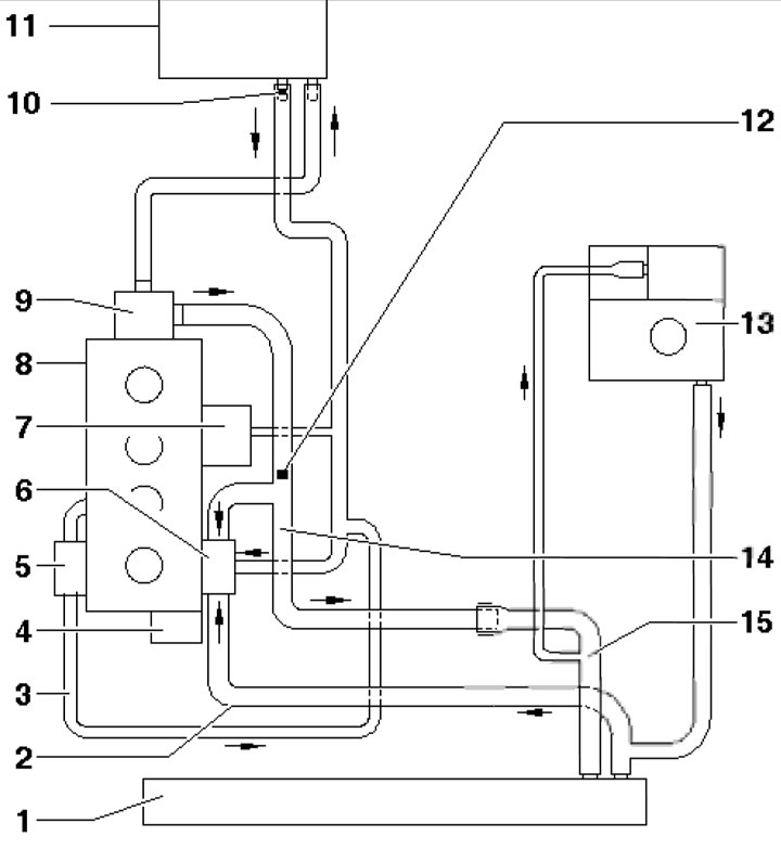
The engine cooling system operates according to the following algorithm. While the engine is not warmed up, the coolant (coolant) is pumped by the water pump only in the cylinder head and block, as well as in the heat exchanger of the climate control system heater (see illustration 1.1). When the coolant temperature rises to a certain level, the thermostat opens a large cooling circuit and the coolant circulates additionally through the radiator, cooling itself with the air passing through it. When the coolant temperature reaches an even higher value, the electric fan of the cooling system turns on, which creates an additional air flow through the radiator fins for more intensive heat removal from it.

1.1a. Engine cooling system diagram using the 2.0 TFSI engine as an example 1. Radiator; 2. Lower…

1.1a. Engine cooling system diagram using the 2.0 TFSI engine as an example 1. Radiator; 2. Lower radiator hose; 3. Turbocharger return hose with bypass valve; 4. Water pump; 5. Turbocharger; 6. Thermostat; 7. Engine oil radiator; 8. Cylinder head and block; 9. Connecting tube; 10. Air bleed hole; 11. Heat exchanger of the climate system; 12. Bleed screw, 12 Nm; 13. Expansion tank; 14. Coolant pipe; 15. Upper radiator hose
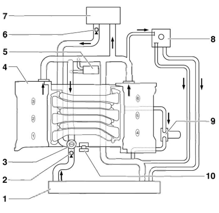


1.1b. Schematic diagram of the engine cooling system using the 3.0 MPI engine as an example 1.…

1.1b. Schematic diagram of the engine cooling system using the 3.0 MPI engine as an example 1. Radiator; 2. Bleed screw, 15 Nm; 3. Thermostat; 4. Cylinder head and block; 5. Throttle body; 6. Air bleed hole; 7. Heat exchanger of the climate system; 8. Expansion tank; 9. Engine oil radiator; 10. Water pump


On 4-cylinder petrol models the thermostat is controlled by the ECM based on the data received from the MAP sensor. On other engines a traditional thermostat is used, which opens when a certain temperature of the coolant directly in contact with the thermostat is reached.

Some engines use two coolant temperature sensors: one (ECT) detects the coolant temperature in the engine cooling system circuit, which is used to calculate the amount of fuel injected and the set idle speed value; another (radiator outlet temperature sensor) determines the coolant temperature after the radiator, which is used to turn on the fan.

Precautionary measures


Before working in the engine compartment, especially in the radiator fan area, be sure to disconnect the negative battery cable and the fan wiring connector, as it may turn on due to thermal conductivity even when the ignition is off.


Do not open the coolant expansion tank or radiator cap until the engine has completely cooled down to avoid being burned by hot liquid or its steam.

If you need to open the expansion tank cap when the engine is hot, wrap it with a rag. Remove the cap slowly, gradually reducing the steam pressure.

Descriptions of checking and adjusting the coolant level, replacing the coolant, and some cooling system checks are provided in Sections 4 and 5 Chapters 1.
The article was checked by auto expert Timur Bazhenov
This article is available at russian, bulgarian, belarusian, ukrainian, serbian, croatian, romanian, polish, slovak, hungarian

Share information:
Previous articles
Audi A4 B7: Cooling system
Next articles

Engine Cooling and Cabin Air Conditioning Systems —…
Replacing the coolant, bleeding the cooling system
Removal and installation the radiator shroud and fan assembly
Removal and installation the radiator
Checking, removing and installing the thermostat


Similar articles on other Audi car models:
Fuel Injection System — Description and Precautions Audi 80 B3 (1986-1991, petrol)
Engine Removal — Methods and Precautions Audi 100 C3 (1982-1990, diesel)
Safety precautions to avoid damage to the catalytic converter Audi A3 Type 8L (1996-2003)
Description of electrical equipment and safety precautions Audi A6 C4 (1994-1997)
General information and precautions Audi Q7 Typ 4L (2005-2015, diesel)
Safety precautions when working with the fuel supply system Audi A2 (1999-2005)
Link to this page in different formats


Visitor comments

No comments yet


How much will 45 + 19 =


A4(B8, 2007-2015) 
  • General information
  • Operating instructions
  • Power unit
  • Petrol engines 1.8 l
  • Petrol engines 1.8/2.0 l
  • Petrol engines 3.0 l
  • Petrol engines 3.2 l
  • Fuel system (petrol)
  • Diesel engines 2.0 l (CA*)
  • Diesel engines 2.0 l (CJCB)
  • Diesel engines 2.7/3.0 l
  • Diesel engines 3.0 l
  • Fuel system (diesel)
  • Transmission
  • Manual gearbox 0B1
  • Manual gearbox 0B2
  • Manual gearbox 0B3
  • Manual gearbox 0B4
  • Automatic transmission 0B5
  • Automatic transmission 0B6
  • Automatic transmission 0AW
  • All-wheel drive system
  • Chassis
  • Front suspension
  • Rear suspension
  • Brake system
  • Steering system
  • Body
  • Exterior
  • Interior
  • Seats
  • Doors, locks and windows
  • Security system
  • Heating and air conditioning
  • Electrical equipment
  • Audio system
  • Power devices
  • Equipment and devices
  • Lighting and lamps
  • Electrical circuits
 
A4(B7, 2004-2008) 
  • General information
  • Introduction to manual
  • Troubleshooting
  • Operating instructions
  • Maintenance
  • Power unit
  • Petrol engines 2.0 (ALT)
  • Petrol engines 2.0 (TFSI)
  • Petrol engines 1.8 (MPI)
  • Diesel engines
  • Cooling system
  • Air conditioner
  • Fuel and exhaust system
  • Ignition system
  • Starting and charging
  • Transmission
  • Clutch
  • Manual gearbox
  • Automatic gearbox
  • Drive shafts
  • Chassis
  • Brake system
  • Front suspension
  • Rear suspension
  • Steering
  • Body
  • Exterior
  • Interior
  • Electrical equipment
  • Equipment and devices
  • Lighting and signaling
  • Windscreen wipers and washers
  • Electrical diagrams
  • Electrical diagrams (since 2007)
 
A4(B6, 2000-2006) 
  • General information
  • Vehicle Description
  • User manual
  • Maintenance
  • Power unit
  • Gasoline engine
  • Diesel engine
  • Lubrication system
  • Cooling system
  • Supply system
  • Injection system
  • Exhaust system
  • Ignition and control
  • Transmission
  • Gear box
  • Clutch and drive shafts
  • Chassis
  • Brake system
  • Car suspension
  • Steering
  • Body
  • Heating and ventilation
  • Exterior (external elements)
  • Interior (internal elements)
  • Electrical equipment
  • Power devices
  • Lighting and appliances
  • Electrical circuits
 
A4(B6, 2000-2006, petrol) 
  • General information
  • Introduction to the guide
  • Car care
  • Power unit
  • Engine repair
  • Lubrication system
  • Cooling system
  • Injection and control system
  • Ignition system
  • Power and exhaust system
  • Transmission
  • Clutch and drive shafts
  • Car gearbox
  • Chassis
  • Suspension and wheels
  • Steering
  • Brake system
  • Body
  • Interior
  • Exterior
  • Electrical equipment
  • Equipment and devices
  • Lighting and signaling
  • Power devices
  • Electrical circuits
 
A4(B5, 1994-2001) 
  • General information
  • Introduction to the guide
  • Car care
  • Maintenance (gasoline)
  • Maintenance (diesel)
  • Power unit
  • Gasoline engines
  • Diesel engines
  • Engine overhaul
  • Cooling system
  • Fuel injection (gasoline)
  • Fuel system (diesel)
  • Exhaust system
  • Ignition system
  • Transmission
  • Clutch
  • Mechanical gearbox
  • Automatic gearbox
  • Drive shafts
  • Chassis
  • Brake system
  • Car suspension
  • Steering
  • Body
  • Exterior
  • Interior
  • Doors, locks and windows
  • Heating and ventilation
  • Electrical equipment
  • Power devices
  • Equipment and devices
  • Electrical circuits
 
A4(B5, 1994-2001, petrol) 
  • General information
  • Vehicle description
  • Maintenance
  • Power unit
  • Engine repair
  • Turbocharging
  • Exhaust system
  • Cooling system
  • Ignition system
  • Fuel system
  • Motronic injection system
  • MPI and MPFI injection system
  • Transmission
  • Clutch
  • Gearbox and shafts
  • Chassis
  • Steering
  • Car suspension
  • Brake system
  • Wheels and tires
  • Body
  • Heating and ventilation
  • Body parts
  • Electrical equipment
  • Fuses and relays
  • Power devices
  • Lighting and lamps
  • Tools and devices
  • Electrical circuits
 
AudiManual.ru © 2017-2026 · Mobile version · Feedback · Sitemap: EN BG BY UA RS HR RO PL SK HU · Site search · News and articles
80 B2 · 80 B3 petrol · 80 B3 · 80 B4 · 100 C3 diesel · 100 C3 petrol · 100 C3 · 100 C4 petrol · 100 C4 · A3 Type 8L · A4 B5 petrol · A4 B5 · A4 B6 petrol · A4 B6 · A4 B7 · A4 B8 · A6 C4 · A6 C5 · A6 C5 Allroad · A8 D2 · Q5 Type 8R · Q7 Typ 4L · Audi A2 ·
This site uses cookies 🍪. Click the button to accept this fact.