
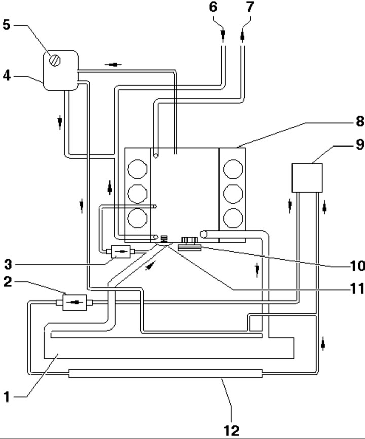
1.1. Cooling system circuit of 3.2 TDI engines of the 1st generation:
1 - Radiator;
2 - Pump "V166" for fuel cooling;
3 - EGR cooler pump "V400" (only on CASA/CASB engines);
4 - Expansion tank;
5 - Filler cap;
6 - From the heater radiator;
7 - To the heater radiator;
8 - Cylinder head and block;
9 - Fuel cooler, on the fuel filter;
10 - Coolant pump;
11 - Thermostat;
12 - Radiator for cooling fuel.
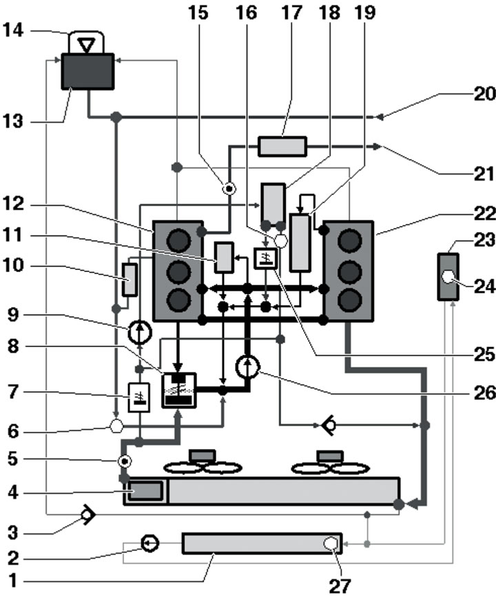
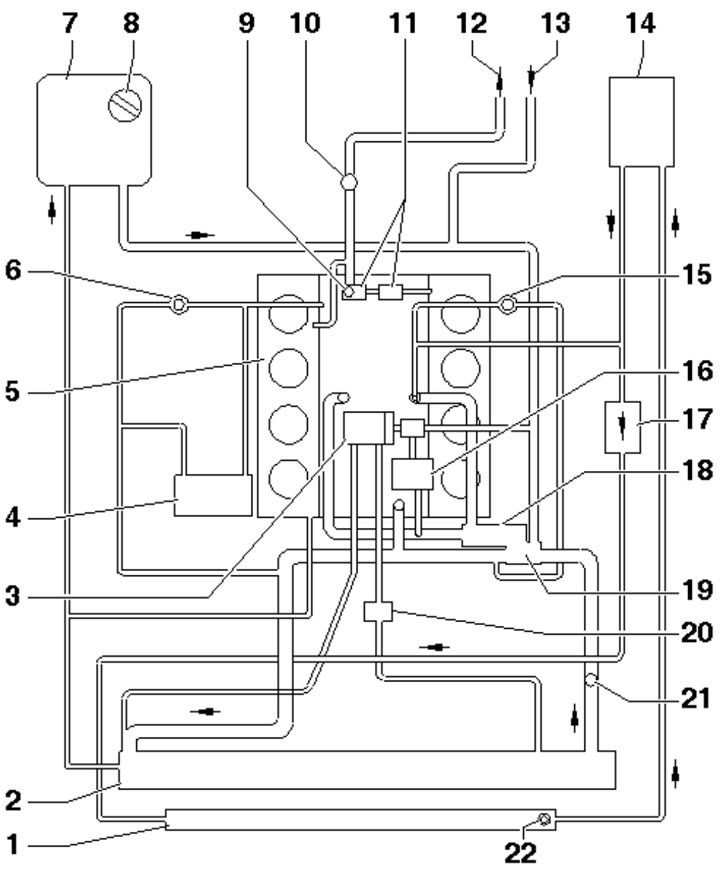
1.2. Cooling system circuit of 3.2 TDI SCR engines:
1 - Radiator for cooling fuel;
2 - Pump "V166" for fuel cooling;
3 - Non-return valve;
4 - Radiator;
5 - Sensor "G83" coolant temperature at the radiator outlet;
6, 16 - Bleed nipple;
7 - Coolant circuit thermostat for EGR;
8 - Thermostat;
9 - EGR radiator pump V400, in the coolant circuit for EGR;
10 - Generator;
11 - Oil cooler;
12 - Right cylinder head;
13 - Expansion tank;
14 - Expansion tank cap;
15 - ECT sensor "G62";
17 - Additional EGR cooler;
18 - EGR radiator;
19 - EGR radiator switching valve;
20 - From the heater radiator;
21 - To the heater radiator;
22 - Left cylinder head;
23 - Fuel cooler, on fuel filter, only up to 05.2010.;
24, 27 - Bleed nipple, only up to 05.2010.;
25 - Thermostat in the coolant circuit for EGR, with EGR activator "V338";
26 - Coolant pump, only up to 05.2010.
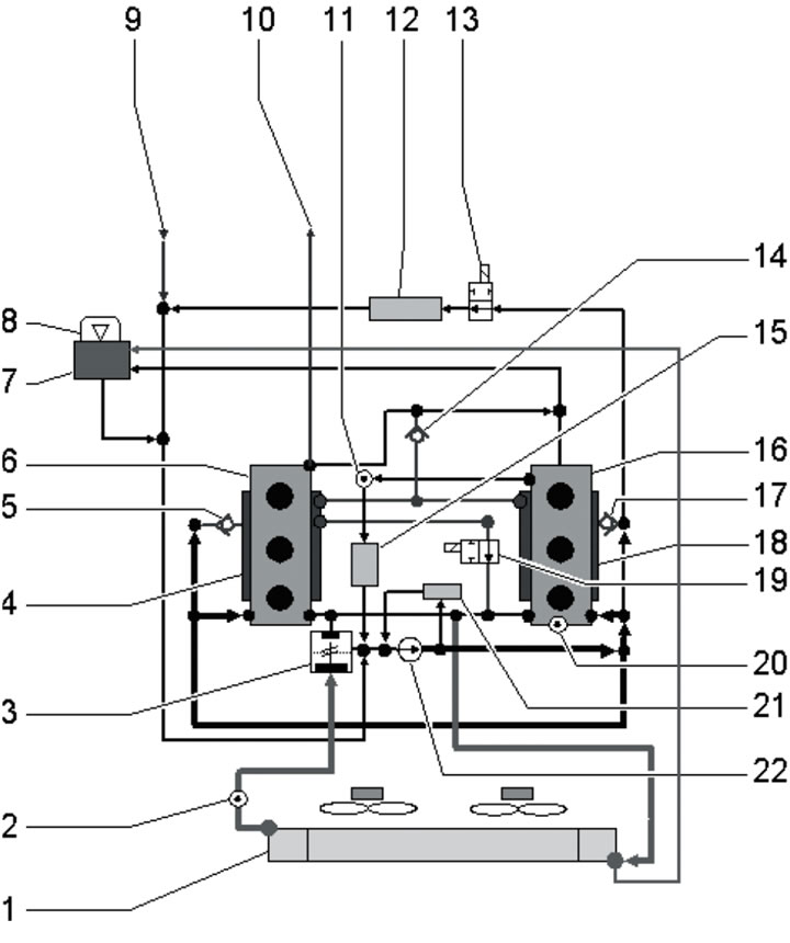
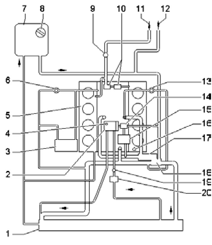
1.3. Cooling system circuit of 2nd generation 3.2 TDI engines:
1 - Radiator;
2 - Sensor "G83" coolant temperature at the radiator outlet;
3 - Thermostat "F265" of the engine cooling system, with electronic control;
4, 18 - Cylinder block;
5, 14, 17 - Non-return valve;
6 - Right cylinder head;
7 - Coolant expansion tank;
8 - Tank lid 7;
9 - From the heater radiator;
10 - To the heater radiator;
11 - ECT sensor "G62";
12 - ATF radiator;
13 - Valve "N488" for supplying coolant for automatic transmission;
15 - EGR radiator;
16 - Left cylinder head;
19 - Fuel shut-off valve;
20 - Temperature sensor "N694" for regulating engine temperature;
21 - Oil cooler;
22 - Coolant pump.
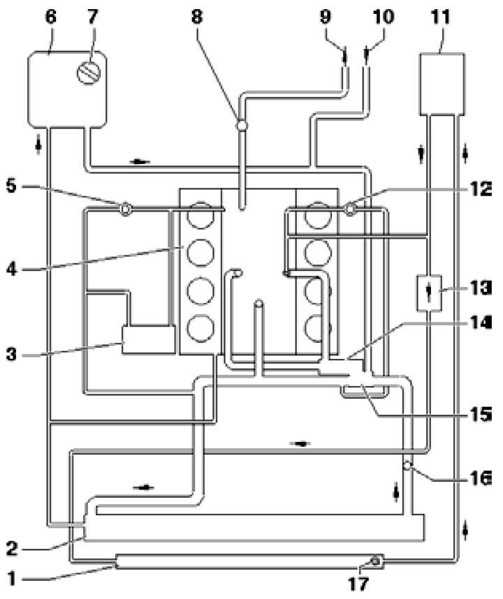
1.4a. Cooling system circuit of 4.2 TDI engines (code BTR):
1 - Radiator for cooling fuel;
2 - Radiator;
3 - Generator;
4 - Cylinder head and block;
5 - Turbocharger of the right bank of cylinders;
6 - Coolant expansion tank;
7 - Tank lid 6;
8 - ECT sensor "G62";
9 - To the heater radiator;
10 - From the heater radiator;
11 - Fuel cooler, on the fuel filter;
12 - Turbocharger of the left bank of cylinders;
13 - Fuel cooling pump "V166";
14 - Coolant pump;
15 - Thermostat;
16 - Sensor "G83" coolant temperature at the radiator outlet;
17 - Bleed hole bolt.
1.4b. Cooling system circuit of 4.2 TDI engines (CCFA code):
1 - Radiator for cooling fuel;
2 - Radiator;
3 - EGR radiator, with thermostat;
4 - Generator;
5 - Cylinder head and block;
6 - Turbocharger of the right bank of cylinders;
7 - Coolant expansion tank;
8 - Tank lid 7;
9, 22 - Bleed hole bolt;
10 - ECT sensor "G62";
11 - Connection for EGR activators "V338" and "V339";
12 - To the heater radiator;
13 - From the heater radiator;
14 - Fuel cooler, on the fuel filter;
15 - Turbocharger of the left bank of cylinders;
16 - Oil cooler;
17 - Fuel cooling pump "V166";
18 - Coolant pump;
19 - Thermostat;
20 - EGR radiator pump "V400";
21 - Sensor "G83" coolant temperature at the radiator outlet.
1.4s. Cooling system circuit of 4.2 TDI engines (CCFC code):
1 - Radiator;
2 - EGR radiator;
3 - Generator;
4 - Bleed hole bolt;
5 - Cylinder head and block;
6 - Turbocharger of the right bank of cylinders;
7 - Coolant expansion tank;
8 - Tank lid 7;
9 - ECT sensor "G62";
10 - Connection for EGR activators "V338" and "V339";
11 - To the heater radiator;
12 - From the heater radiator;
13 - Turbocharger of the left bank of cylinders;
14 - Coolant circuit thermostat for EGR;
15 - Oil cooler;
16 - Temperature sensor "G694" for regulating engine temperature;
17 - Coolant pump, with vacuum block;
18 - Thermostat;
19 - EGR temperature sensor "G98";
20 - EGR radiator pump "V400".
Installation details for individual components are provided in the relevant sections.
The engine cooling system operates according to the following algorithm. Until the engine is warmed up, the coolant (coolant) is pumped by a water pump only in the cylinder head and block, as well as in the interior heater heat exchanger. This way the engine warms up quickly. When the coolant temperature rises to a certain value (controlled by the ECT sensor) the thermostat opens a large cooling circuit and the coolant circulates additionally through the radiator, being cooled by the air passing through it. In this way, the engine's operating temperature is maintained. When the coolant temperature reaches an even higher value, the cooling system fan turns on, which begins to create an additional air flow through the radiator fins to more intensively remove heat from it.
In addition to the heater radiator, the cooling system circuit may include an oil cooler (see Chapter 2), fuel cooler (see Chapter 4), power steering fluid cooler (see Chapter 9), additional heater radiator (if available, see Part B), aTF radiator (see Chapter 6) and EGR radiator (see Chapter 4).
The coolant pump, or water pump, is driven by:
- On 3.2 TDI engines - auxiliary drive belt;
- On 4.2 TDI engines - a separate shaft from the auxiliary drive mechanism.
Precautionary measures
Before working in the engine compartment, especially in the radiator fan area, be sure to disconnect the negative battery cable and the fan wiring connector, as the fan may turn on due to thermal conductivity even when the ignition is off.
Do not open the coolant expansion tank cap until the engine has completely cooled down to avoid being burned by hot liquid or its steam.
If you need to open the expansion tank cap while the engine is hot, wrap it with a rag. Unscrew the cap slowly, gradually releasing the steam pressure.
(This publication is borrowed from the resource AUDImanual)