
Table of contents: 2.0 TFSI engines ↓ 2.0 MPI engine ↓ Engines 1.6 and 1.8 l ↓ Petrol engine 3.0 l ↓ Petrol engine 3.2 l ↓ 4-cylinder diesel engines ↓
2.0 TFSI engines
1. The thermostat installation details are shown in the illustration. To check the thermostat, follow the steps in paragraphs 2-4. To remove the thermostat, go to paragraph 5.
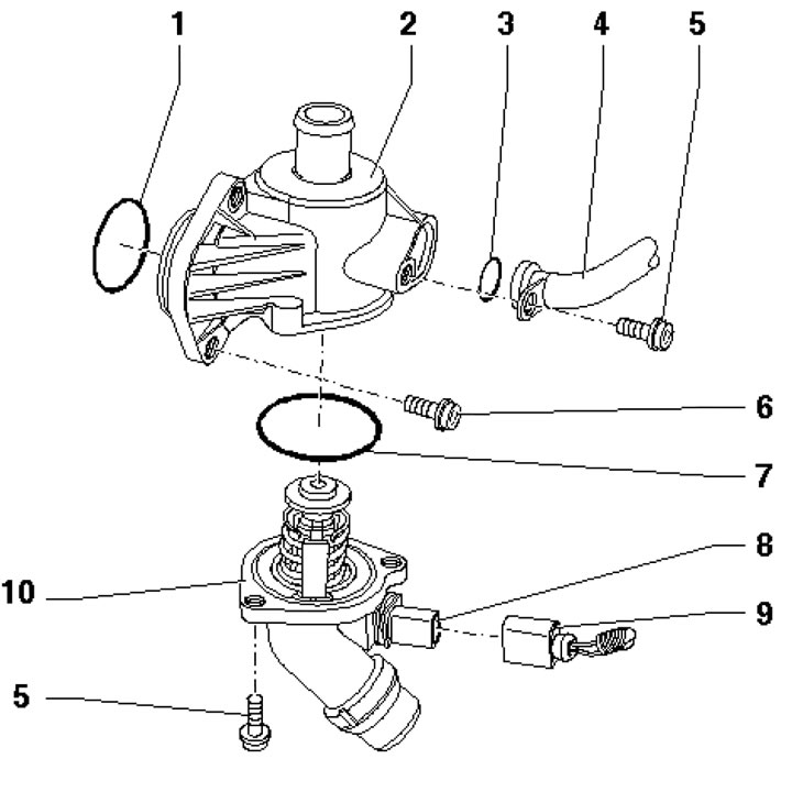
5.1 Thermostat installation details 1, 3. Sealing ring, subject to replacement; 2. Coolant distributor; 4. Lower coolant hose; 5/6. Bolt, 10 // 15 Nm; 7. Gasket, subject to replacement; 8. Heating element connector; 9. Electrical wiring connector; 10. Thermostat
2. Measure the resistance at the thermostat contacts at a temperature of 25°C - it should be 14÷16 Ohm. Otherwise, replace the thermostat.
3. Make sure the sealing ring (see illustration) fits tightly to the thermostat housing around the entire circumference. Otherwise, replace the thermostat.
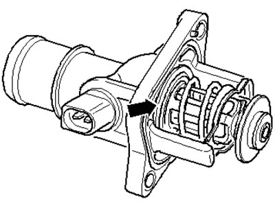
5.3. Checking the thermostat seal
4. Apply 12 V to the thermostat contacts and lower the thermostat up to the flange into a container with boiling coolant. In this case, the wax in the thermostat is additionally heated by electricity. After 10 minutes, the thermostat valve should extend at least 7 mm (and in the illustration). Otherwise, replace the thermostat.
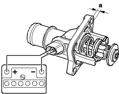
5.4. Checking the thermostat valve stroke
5. Disconnect the negative cable from the battery.
6. Remove the upper engine cover and unscrew the expansion tank cap.
7. Drain the coolant (see Section 2).
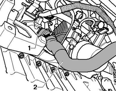
8. Disconnect the electrical wiring connector (1 in the illustration) engine oil pressure sensor, disconnect the lower coolant hose from the tube (2) and drain the remaining coolant.
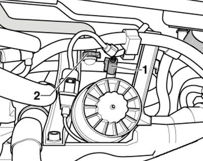
5.8. Oil pressure sensor connector and lower coolant hose
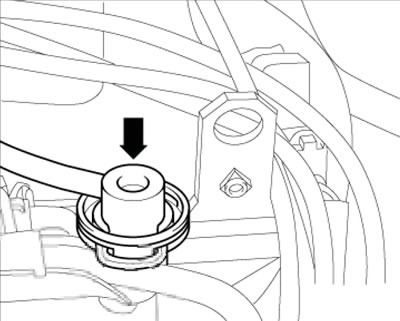
9. Pull the EVAP canister up out of the holder (see illustration) and set it aside without disconnecting the tubes.
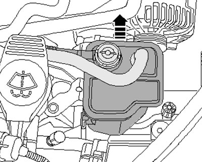
5.9. Removing the EVAP canister
10. Remove the accessory drive belt and its tensioner (see Chapter 2).
11. Remove the generator (see Chapter 5).
12. Disconnect the connector (1 in illustration 5.49 Chapter 2) refrigeration unit compressor couplings, unscrew the bolts (arrows) securing the compressor to the bracket and tie the compressor to the side with a wire without disconnecting the refrigerant lines from it.
13. Disconnect the coolant hose (2 in the illustration), by pulling out the lock (1).
5.13. Coolant hose
14. Remove the bolts (1-6 in Illustration 21.9 Chapter 2) and remove the accessory bracket.
15. Disconnect the connector (1 in the illustration), unscrew the bolts (arrows) and remove the thermostat.
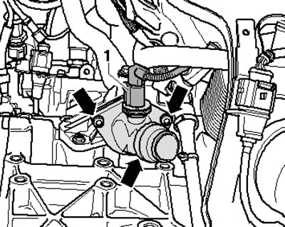
5.15. Thermostat mounting
16. Installation is carried out in the reverse order of dismantling the components.
2.0 MPI engine
17. The thermostat installation details are shown in Illustration 5.1. To check the thermostat, follow the steps in paragraphs 2-4. The procedure for removing the thermostat is described below.
18. Drain the coolant (see Section 2).
19. Disconnect the air hoses at the locations shown in the illustrations 13.6 and 5.28 Chapter 2, and also in the illustration.
5.19. Fastening the air hose to the throttle body
20. Disconnect the hose from the fuel pressure regulator (see illustration).
5.20. Hose on the fuel pressure regulator
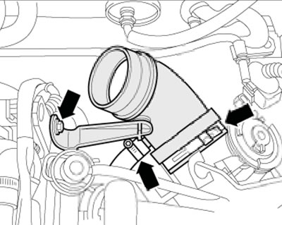
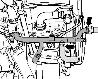
21. Remove the bolts (1 and 2 in the illustration) and separate the upper coolant pipe from the coolant hoses (arrows).
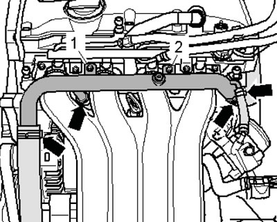
5.21. Fastening the upper coolant pipe
22. Remove the intake manifold (see Chapter 4).
23. Remove the bolts (3 in the illustration) and remove the resonator. Disconnect the hoses (arrows) from the lower coolant pipe, unscrew the bolts (1 and 2) and remove the lower coolant pipe.
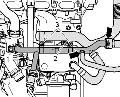
5.23. Removing the lower coolant pipe
24. Disconnect the connector (5 in the illustration), disconnect the hoses (1 and 4), unscrew the bolts (2 and 3) and remove the thermostat housing.
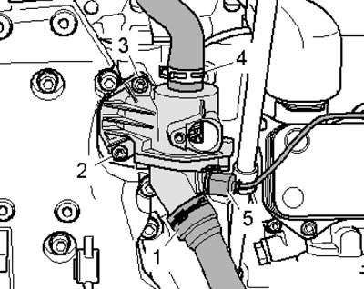
5.24. Removing the thermostat housing
25. Remove the bolts (5 in illustration 5.1) and remove the thermostat (10) with the gasket (7) from the housing (2).
26. Installation is carried out in the reverse order of dismantling the components. Use new sealing rings.
Engines 1.6 and 1.8 l
27. The thermostat installation details are shown in Illustration 5.1. To check the thermostat, follow the steps in paragraphs 2-4. The procedure for removing the thermostat is described below.
28. Drain the coolant (see Section 2).
29. Remove the intake manifold support (see illustration 31.5 Chapter 2).
30. Move the electrical wiring away from the lower coolant pipe, disconnect the coolant hoses from this pipe (arrows in the illustration), unscrew the bolts (1 and 2) and remove the lower coolant pipe from the thermostat housing.
5.30. Fastening the lower coolant pipe
31. Perform the actions described in paragraphs 24-26.
Petrol engine 3.0 l
32. The details of the thermostat and water pump installation are shown in the illustration.
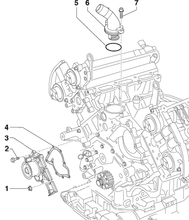
5.32. Thermostat and water pump installation details for 3.0 MPI engine 1/2. Nut/bolt, 10 Nm; 3. Water pump; 4. Gasket, subject to replacement; 5. Sealing ring, subject to replacement; 6. Thermostat; 7. Bolt, 10 Nm
33. Drain the coolant (see Section 2).
34. Remove the intake manifold (see Chapter 4).
35. Remove the bolts (1 and 2 in the illustration), loosen the clamps (arrows) and remove the coolant hose, then remove the thermostat.
36. Installation is carried out in the reverse order of dismantling the components. Use a new sealing ring.
Petrol engine 3.2 l
37. The details of the thermostat and water pump installation are shown in the illustration.
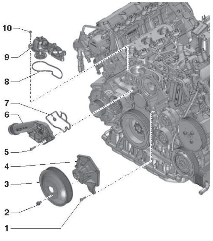
5.37. Details of the installation of the thermostat of the 3.2 FSI engine 1//2. Bolt, 9 //20 Nm; 3. Water pump pulley; 4. Water pump; 5. Bolt, 9 Nm; 6. Connecting coolant hoses; 7, 8. Gasket, subject to replacement; 9. Thermostat; 10. Bolt, 9 Nm
38. Remove the front decorative engine cover (see Chapter 2).
39. Remove the air cleaner air intake (see Section 16 Chapter 1).
40. Drain the coolant (see Section 2).
41. Remove the front bumper cover (see Chapter 11).
42. Bring the radiator frame to the service position (see Chapter 2).
43. Remove the upper section of the intake manifold (see Chapter 4) and the front water pipe.
44. Remove the bolts (10 in illustration 5.37) and remove the thermostat.
45. Installation is carried out in the reverse order of dismantling the components.
4-cylinder diesel engines
46. Remove the top engine cover (see Chapter 2).
47. Drain the coolant (see Section 2).
48. Disconnect the coolant hose from the thermostat housing (see illustration 29.15 Chapter 2).
49. Remove the bolts (1 in the illustration) thermostat housing fasteners (2) and remove it together with the thermostat (4) and sealing ring (3).
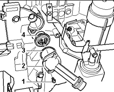
5.49. Thermostat housing installation details
50. Turn the thermostat (2 in the illustration) approximately 90° counterclockwise and remove it from the housing. Replace the sealing ring (1)
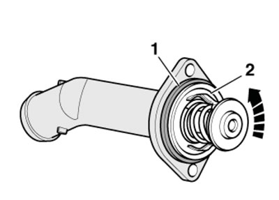
5.50. Removing the thermostat
51. Installation is carried out in the reverse order of dismantling the components. Use a new sealing ring.
(This article was copied from an online resource: audimanual)